Toyota CH-R Service Manual: Front Passenger Side Door Entry Lock and Unlock Functions do not Operate
DESCRIPTION
If the entry lock and unlock functions do not operate for the front passenger door only, the request code may not be being transmitted from the front passenger door or the front door outside handle assembly RH (touch sensor) may be malfunctioning. If the entry functions for other doors operate properly, communication between the electrical key transmitter sub-assembly and electrical key and TPMS receiver assembly is normal. In this case, there may be a problem with request code transmission (communication between the certification ECU (smart key ECU assembly) and front door outside handle assembly RH (electrical key antenna)), or there may be wave interference.
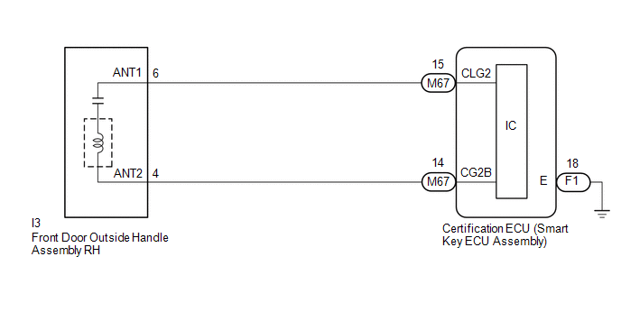
WIRING DIAGRAM
CAUTION / NOTICE / HINT
NOTICE:
- The smart key system (for Entry Function) uses the LIN communication
system and CAN communication system. Inspect the communication function
by following How to Proceed with Troubleshooting. Troubleshoot the smart
key system (for Entry Function) after confirming that the communication
systems are functioning properly.
Click here
.gif)
- When using the Techstream with the engine switch off, connect the Techstream to the DLC3 and turn a courtesy light switch on and off at intervals of 1.5 seconds or less until communication between the Techstream and the vehicle begins. Then select the vehicle type under manual mode and enter the following menus: Body Electrical / Smart Key. While using the Techstream, periodically turn a courtesy light switch on and off at intervals of 1.5 seconds or less to maintain communication between the Techstream and the vehicle.
- Check that there are no electrical key transmitter sub-assemblies in the vehicle.
- Before replacing the certification ECU (smart key ECU assembly), refer
to Precaution.
Click here
- After repair, confirm that no DTCs are output.
PROCEDURE
|
1. |
CHECK POWER DOOR LOCK CONTROL SYSTEM |
(a) When the door control switch on the multiplex network master switch assembly is operated, check that the doors unlock and lock according to the switch operation.
Click here
OK:
Door locks operate normally.
| NG | .gif) |
GO TO POWER DOOR LOCK CONTROL SYSTEM |
|
.gif)
|
2. |
CHECK FOR DTC |
(a) Check for DTCs.
Body Electrical > Smart Key > Trouble Codes|
Result |
Proceed to |
|---|---|
|
DTCs are not output |
A |
|
DTCs are output |
B |
| B | |
GO TO DIAGNOSTIC TROUBLE CODE CHART |
|
|
3. |
CHECK WAVE ENVIRONMENT |
|
(a) Bring the electrical key transmitter sub-assembly approximately 0.7 to 1 m (2.30 to 3.28 ft.) from the front door outside handle assembly RH and perform an entry function check. Click here HINT:
|
|

|
Result |
Proceed to |
|---|---|
|
Entry function does not operate normally |
A |
|
Entry function operates normally |
B |
| B | |
AFFECTED BY WAVE INTERFERENCE |
|
|
4. |
READ VALUE USING TECHSTREAM (P-DOOR TOUCH SENSOR) |
(a) Turn the engine switch off.
(b) Open and close the front passenger door.
(c) With the electrical key transmitter sub-assembly outside of the vehicle, press the lock switch of the electrical key transmitter sub-assembly to lock all of the doors.
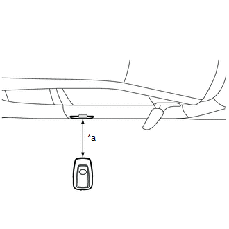
(d) Hold the electrical key transmitter sub-assembly at the same height as the door outside handle assembly and approximately 0.7 to 1 m (2.30 to 3.28 ft.) from the front passenger door.
(e) Check that the LED of the electrical key transmitter sub-assembly blinks.
(f) Read the Data List according to the display on the Techstream.
|
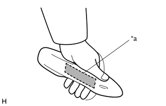
(g) Touch the unlock sensor on the backside of the front door outside handle assembly RH. HINT: When checking the operation of the unlock sensor again, make sure to perform the procedure from step (a). Body Electrical > Smart Key > Data List
OK: The Techstream display changes correctly in response to the operation of the front door outside handle assembly RH. |
|
| NG | |
GO TO STEP 7 |
|
|
5. |
READ VALUE USING TECHSTREAM (P-DOOR TRIGGER SWITCH) |
(a) Turn the engine switch off.
(b) Open and close the front passenger door.
(c) Hold the electrical key transmitter sub-assembly at the same height as the door outside handle assembly and approximately 0.7 to 1 m (2.30 to 3.28 ft.) from the front passenger door.
(d) Read the Data List according to the display on the Techstream.
|
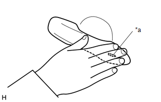
(e) Touch the lock sensor of the front door outside handle assembly RH. HINT:
HINT: When checking the operation of the entry lock function several times, it can be operated up to 2 times consecutively. To operate the function 3 times or more consecutively, the doors need to be unlocked once. However, this is only for the entry lock function, other door lock operations, such as a wireless door lock operation can be performed consecutively. OK: The Techstream display changes correctly in response to the operation of the front door outside handle assembly RH. |
|
| NG | |
GO TO STEP 7 |
|
|
6. |
CHECK KEY DIAGNOSTIC MODE |
(a) Check the following antenna in key diagnostic mode.
Body Electrical > Smart Key > Utility|
Tester Display |
|---|
|
Communication Check(Key Diag Mode) |
(b) Select either channel 1 or channel 2 and perform key diagnostic mode inspection for each channel.
|
(1) Check the electrical key antenna (for front passenger door): When the electrical key transmitter sub-assembly is brought within 0.7 to 1 m (2.30 to 3.28 ft.) of the front door outside handle assembly RH, check that the wireless buzzer sounds. HINT:
|
|
|
Result |
Proceed to |
|---|---|
|
Wireless buzzer does not sound |
A |
|
Wireless buzzer sounds |
B |
| B | |
REPLACE CERTIFICATION ECU (SMART KEY ECU ASSEMBLY) |
|
|
7. |
CHECK HARNESS AND CONNECTOR (CERTIFICATION ECU (SMART KEY ECU ASSEMBLY) - FRONT DOOR OUTSIDE HANDLE ASSEMBLY RH) |
(a) Disconnect the M67 certification ECU (smart key ECU assembly) connector.
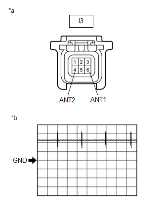
(b) Disconnect the I3 front door outside handle assembly RH connector.
(c) Measure the resistance according to the value(s) in the table below.
Standard Resistance:
|
Tester Connection |
Condition |
Specified Condition |
|---|---|---|
|
M67-15 (CLG2) - I3-6 (ANT1) |
Always |
Below 1 Ω |
|
M67-14 (CG2B) - I3-4 (ANT2) |
Always |
Below 1 Ω |
|
M67-15 (CLG2) or I3-6 (ANT1) - Body ground |
Always |
10 kΩ or higher |
|
M67-14 (CG2B) or I3-4 (ANT2) - Body ground |
Always |
10 kΩ or higher |
(d) Reconnect the M67 certification ECU (smart key ECU assembly) connector.
| NG | |
REPAIR OR REPLACE HARNESS OR CONNECTOR |
|
|
8. |
CHECK CERTIFICATION ECU (SMART KEY ECU ASSEMBLY) (OUTPUT TO FRONT PASSENGER DOOR ELECTRICAL KEY ANTENNA) |
|
(a) Using an oscilloscope, check the waveform. OK:
*: For details about the entry function detection area, refer to Operation Check. Click here |
|
| NG | |
REPLACE CERTIFICATION ECU (SMART KEY ECU ASSEMBLY) |
|
|
9. |
CHECK ENTRY LOCK OPERATION |
(a) Connect all connectors and check that the function operates normally.
Click here
|
Result |
Proceed to |
|---|---|
|
Entry function does not operate normally |
A |
|
Entry function operates normally |
B |
| B | |
END (CONNECTOR WAS NOT CONNECTED SECURELY) |
|
|
10. |
REPLACE FRONT DOOR OUTSIDE HANDLE ASSEMBLY RH |
(a) Replace the front door outside handle assembly RH with a new one or the front door outside handle assembly LH if it is functioning properly.
Click here
|
|
11. |
CHECK ENTRY LOCK OPERATION |
(a) Check that the function operates normally.
Click here
|
Result |
Proceed to |
|---|---|
|
Entry function operates normally |
A |
|
Entry function does not operate normally |
B |
| A | |
END (FRONT DOOR OUTSIDE HANDLE ASSEMBLY RH WAS DEFECTIVE) |
| B | |
REPLACE CERTIFICATION ECU (SMART KEY ECU ASSEMBLY) |
 Front Passenger Side Door Entry Unlock Function does not Operate
DESCRIPTION
If the entry unlock function does not operate for the front passenger door only,
but the entry lock function operates, the request code is being transmitted properly
from the front pa ...
 Driver Side Door Entry Lock Function does not Operate
DESCRIPTION
If the entry lock function does not operate for the driver door only, but the
entry unlock function operates, the request code is being transmitted properly from
the driver door. In t ...
Other materials:
Toyota CH-R Service Manual > Smart Key System(for Start Function): Engine/Power Switch Malfunction (B2278)
DESCRIPTION
This DTC is stored when the SSW1 contact signal and SSW2 contact signal, which
are detected when the engine switch is operated, do not match.
DTC No.
Detection Item
DTC Detection Condition
Trouble Area
Note
B2278 ...
Toyota CH-R Service Manual > Power Steering System: Vehicle Speed Signal (C1541)
DESCRIPTION
The power steering ECU assembly receives vehicle speed signals from the skid
control ECU (brake actuator assembly) via CAN communication. The ECU provides appropriate
assist force in accordance with the vehicle speed based on the signals.
DTC No.
Detection Ite ...
Toyota C-HR (AX20) 2023-2026 Owner's Manual
Toyota CH-R Owners Manual
- For safety and security
- Instrument cluster
- Operation of each component
- Driving
- Interior features
- Maintenance and care
- When trouble arises
- Vehicle specifications
- For owners
Toyota CH-R Service Manual
- Introduction
- Maintenance
- Audio / Video
- Cellular Communication
- Navigation / Multi Info Display
- Park Assist / Monitoring
- Brake (front)
- Brake (rear)
- Brake Control / Dynamic Control Systems
- Brake System (other)
- Parking Brake
- Axle And Differential
- Drive Shaft / Propeller Shaft
- K114 Cvt
- 3zr-fae Battery / Charging
- Networking
- Power Distribution
- Power Assist Systems
- Steering Column
- Steering Gear / Linkage
- Alignment / Handling Diagnosis
- Front Suspension
- Rear Suspension
- Tire / Wheel
- Tire Pressure Monitoring
- Door / Hatch
- Exterior Panels / Trim
- Horn
- Lighting (ext)
- Mirror (ext)
- Window / Glass
- Wiper / Washer
- Door Lock
- Heating / Air Conditioning
- Interior Panels / Trim
- Lighting (int)
- Meter / Gauge / Display
- Mirror (int)
- Power Outlets (int)
- Pre-collision
- Seat
- Seat Belt
- Supplemental Restraint Systems
- Theft Deterrent / Keyless Entry

0.0084