Toyota CH-R Service Manual: Transmission Fluid Temperature Sensor "A" Circuit Low Input (P0712,P0713)
DESCRIPTION
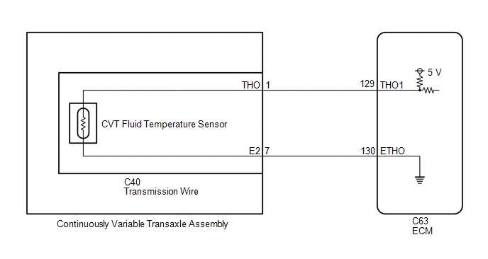
The CVT fluid temperature sensor converts the fluid temperature into a resistance value which is detected by the ECM.
The sensor resistance changes with the CVT fluid temperature. As the temperature rises, the sensor resistance decreases. The ECM applies voltage to the temperature sensor through ECM terminal THO1 and calculates the fluid temperature based on the voltage signal.
HINT:
The CVT fluid temperature is likely to increase under conditions such as towing, climbing hills and in traffic.
|
DTC No. |
Detection Item |
DTC Detection Condition |
Trouble Area |
MIL |
Memory |
|---|---|---|---|---|---|
|
P0712 |
Transmission Fluid Temperature Sensor "A" Circuit Low Input |
There is a short in the CVT fluid temperature sensor circuit for 0.5 seconds (1 trip detection logic). |
|
Comes on |
DTC stored |
|
P0713 |
Transmission Fluid Temperature Sensor "A" Circuit High Input |
Either one of the following conditions is met (1 trip detection logic):
|
|
Comes on |
DTC stored |
MONITOR DESCRIPTION
The CVT fluid temperature sensor converts the CVT fluid temperature to an electrical resistance value. Based on the resistance, the ECM determines the CVT fluid temperature and detects an open or short circuit in the CVT fluid temperature circuit. If the resistance value of the CVT fluid temperature is below 79 Ω*1 or higher than 156 kΩ*2, the ECM interprets this as a fault in the CVT fluid sensor or wiring. The ECM illuminates the MIL and stores a DTC.
*1: 150°C (302°F) or higher is indicated regardless of the actual CVT fluid temperature.
*2: -40°C (-40°F) is indicated regardless of the actual CVT fluid temperature.
HINT:
The CVT fluid temperature can be checked on the Techstream display.
MONITOR STRATEGY
|
Related DTCs |
P0712: CVT fluid temperature sensor / Range check (Low voltage) P0713: CVT fluid temperature sensor / Range check (High voltage) |
|
Required sensors/Components |
Continuously variable transaxle assembly (CVT fluid temperature sensor) |
|
Frequency of operation |
Continuous |
|
Duration Conditions |
0.5 seconds |
|
MIL operation |
Immediately |
|
Sequence of operation |
None |
TYPICAL ENABLING CONDITIONS
All|
Battery voltage |
8 V or more |
|
Time after Battery voltage 8 V or more |
0.5 seconds or more |
|
Write Inhibit |
permit |
|
Time after Write status forbiddance to permit |
0.5 seconds or more |
|
Ignition switch |
ON |
|
Time after Ignition switch OFF to ON |
0.5 seconds or more |
|
Starter |
OFF |
|
Time after Starter ON to OFF |
0.5 seconds or more |
|
The monitor will run whenever the following DTCs are not present. |
None |
|
Engine coolant temperature (ECT) or intake air temperature (IAT) at engine start. |
-29.375°C (-20.875°F) or less |
|
Time after engine start |
10 minutes |
|
ECT (Engine coolant temperature) Sensor circuit fail (Pending + MIL) (P0115, P0117, P0118) |
Not detected |
|
IAT (Intake air temperature) Sensor circuit fail (Pending + MIL) (P00AC, P00AD, P0110, P0112, P0113) |
Not detected |
|
Engine coolant temperature (ECT) or intake air temperature (IAT) at engine start. |
More than -29.375°C (-20.875°F) |
|
Time after engine start |
10 seconds |
|
ECT (Engine coolant temperature) Sensor circuit fail (Pending + MIL) (P0115, P0117, P0118) |
Not detected |
|
IAT (Intake air temperature) Sensor circuit fail (Pending + MIL) (P00AC, P00AD, P0110, P0112, P0113) |
Not detected |
TYPICAL MALFUNCTION THRESHOLDS
P0712:|
CVT fluid temperature sensor voltage CVT fluid temperature sensor output temperature) |
Less than 0.14 V (Higher than 164°C (327.2°F)) |
|
CVT fluid temperature sensor voltage CVT fluid temperature sensor output temperature) |
More than 4.91 V (Less than -48°C (-54.4°F) |
COMPONENT OPERATING RANGE
|
CVT fluid temperature sensor voltage CVT fluid temperature sensor output temperature) |
0.14 to 4.91 V (-48 to 164°C (-54.4 to 327.2°F) |
WIRING DIAGRAM
CAUTION / NOTICE / HINT
NOTICE:
- Perform initialization when parts related to the continuously variable
transaxle are replaced.
Click here
.gif)
- Check that no DTCs are stored after performing initialization.
Click here
- Perform the universal trip to clear permanent DTCs.
Click here
HINT:
After performing repair, clear the DTCs and perform the following procedure to check that DTCs are not output.
- Start the engine and wait for 15 minutes or more.
- Check for DTCs again.
Click here
PROCEDURE
|
1. |
READ VALUE USING TECHSTREAM (A/T OIL TEMPERATURE 1) |
(a) Warm up the engine.
(b) Connect the Techstream to the DLC3.
(c) Turn the ignition switch to ON.
(d) Turn the Techstream on.
(e) Enter the following menus: Powertrain / Engine and ECT / Data List.
Powertrain > Engine and ECT > Data List|
Tester Display |
|---|
|
A/T Oil Temperature 1 |
(f) In accordance with the display on the Techstream, read the Data List.
Powertrain > Engine and ECT > Data List|
Tester Display |
Measurement Item |
Range |
Normal Condition |
Diagnostic Note |
|---|---|---|---|---|
|
A/T Oil Temperature 1 |
CVT fluid temperature sensor value |
Min.: -40°C (-40°F) Max.: 150°C (302°F) |
|
If the value is -40°C (-40°F) or 150°C (302°F) or higher, the CVT fluid temperature sensor circuit is open or shorted. |
|
Result |
Proceed to |
|---|---|
|
Data display is not within Normal Condition range |
A |
|
Data display is within Normal Condition range |
B |
| B | .gif) |
GO TO STEP 6 |
|
.gif)
|
2. |
INSPECT TRANSMISSION WIRE (CVT FLUID TEMPERATURE SENSOR) |
|
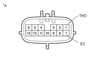
(a) Disconnect the C40 transmission wire connector. |
|
(b) Measure the resistance according to the value(s) in the table below.
Standard Resistance:
|
Tester Connection |
Condition |
Specified Condition |
|---|---|---|
|
1 (THO) - 7 (E2) |
Always |
79 Ω to 156 kΩ |
|
1 (THO) - Body ground and other terminals |
Always |
10 kΩ or higher |
|
7 (E2) - Body ground and other terminals |
Always |
10 kΩ or higher |
HINT:
If the resistance is outside the specified range at any of the CVT fluid temperatures shown in the table below, the driveability of the vehicle may be affected.
|
CVT Fluid Temperature |
Specified Condition |
|---|---|
|
10°C (50°F) |
5.6 to 7.3 kΩ |
|
25°C (77°F) |
3.5 kΩ |
|
110°C (230°F) |
0.22 to 0.27 kΩ |
| NG | |
GO TO STEP 5 |
|
|
3. |
CHECK HARNESS AND CONNECTOR (TRANSMISSION WIRE - ECM) |
|
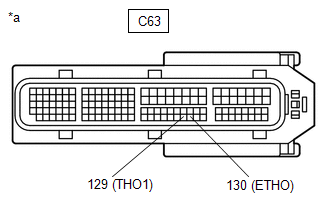
(a) Disconnect the ECM connector. |
|
(b) Measure the resistance according to the value(s) in the table below.
Standard Resistance:
|
Tester Connection |
Condition |
Specified Condition |
|---|---|---|
|
C63-129 (THO1) - C63-130 (ETHO) |
Always |
79 Ω to 156 kΩ |
|
C63-129 (THO1) - Body ground and other terminals |
Always |
10 kΩ or higher |
|
C63-130 (ETHO) - Body ground and other terminals |
Always |
10 kΩ or higher |
| NG | |
REPAIR OR REPLACE HARNESS OR CONNECTOR (TRANSMISSION WIRE - ECM) |
|
|
4. |
REPLACE ECM |
(a) Replace the ECM.
Click here
| NEXT | |
PERFORM INITIALIZATION |
|
5. |
REPLACE CONTINUOUSLY VARIABLE TRANSAXLE ASSEMBLY |
(a) Replace the continuously variable transaxle assembly.
- When Not Using the Engine Support Bridge
Click here
- When Using the Engine Support Bridge
Click here
| NEXT | |
PERFORM INITIALIZATION |
|
6. |
REPLACE ECM |
(a) Replace the ECM.
Click here
| NEXT | |
PERFORM INITIALIZATION |
 Input / Turbine Speed Sensor "A" Circuit No Signal (P0717,P07BF,P07C0)
DESCRIPTION
The ECM receives a signal from the transmission revolution sensor (NT) installed
in the continuously variable transaxle to control the lock-up engagement pressure
and forward and reve ...
 Output Speed Sensor Circuit No Signal (P0722,P077C,P077D)
DESCRIPTION
The ECM receives a signal from the transmission revolution sensor (NOUT) installed
in the continuously variable transaxle and determines the output shaft (secondary
pulley) speed in o ...
Other materials:
Toyota CH-R Service Manual > Blind Spot Monitor System: Diagnosis System
DIAGNOSIS SYSTEM
DESCRIPTION
(a) Blind spot monitor data and Diagnostic Trouble Codes (DTCs) can be read from
the Data Link Connector 3 (DLC3) of the vehicle. When the system seems to be malfunctioning,
use the Techstream to check for malfunctions and to perform repairs.
CHECK DLC3
(a) Check ...
Toyota CH-R Service Manual > Lighting System: Diagnostic Trouble Code Chart
DIAGNOSTIC TROUBLE CODE CHART
Lighting System
DTC No.
Detection Item
Note
Link
B1244
Light Sensor Circuit Malfunction
-
B242C
Right Headlight ECU Malfunction
...
Toyota CH-R Owners Manual
- For safety and security
- Instrument cluster
- Operation of each component
- Driving
- Interior features
- Maintenance and care
- When trouble arises
- Vehicle specifications
- For owners
Toyota CH-R Service Manual
- Introduction
- Maintenance
- Audio / Video
- Cellular Communication
- Navigation / Multi Info Display
- Park Assist / Monitoring
- Brake (front)
- Brake (rear)
- Brake Control / Dynamic Control Systems
- Brake System (other)
- Parking Brake
- Axle And Differential
- Drive Shaft / Propeller Shaft
- K114 Cvt
- 3zr-fae Battery / Charging
- Networking
- Power Distribution
- Power Assist Systems
- Steering Column
- Steering Gear / Linkage
- Alignment / Handling Diagnosis
- Front Suspension
- Rear Suspension
- Tire / Wheel
- Tire Pressure Monitoring
- Door / Hatch
- Exterior Panels / Trim
- Horn
- Lighting (ext)
- Mirror (ext)
- Window / Glass
- Wiper / Washer
- Door Lock
- Heating / Air Conditioning
- Interior Panels / Trim
- Lighting (int)
- Meter / Gauge / Display
- Mirror (int)
- Power Outlets (int)
- Pre-collision
- Seat
- Seat Belt
- Supplemental Restraint Systems
- Theft Deterrent / Keyless Entry

0.0172