Toyota CH-R Service Manual: Transmission Range Sensor Circuit (PRNDL Input) (P0705)
DESCRIPTION
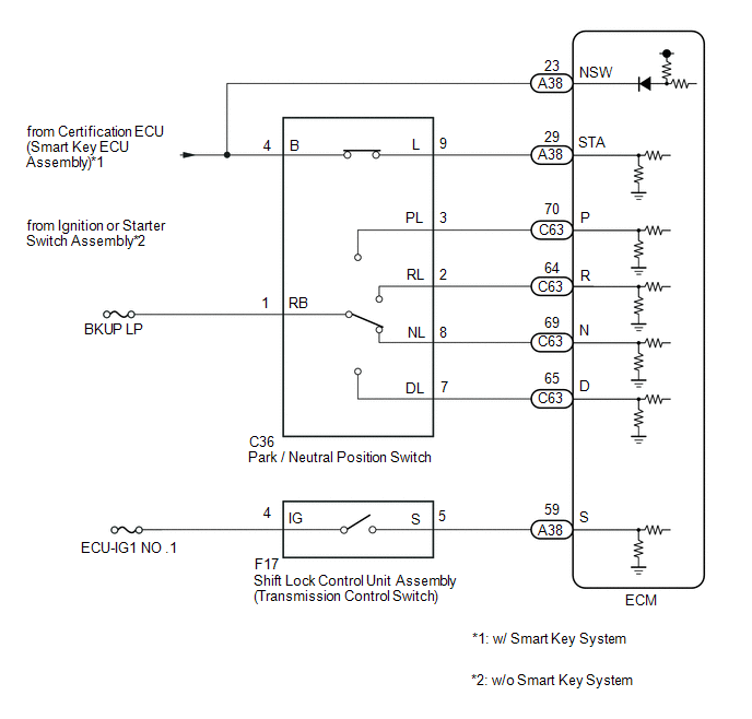
The park/neutral position switch and transmission control switch (shift lock control unit assembly) detect the shift lever position and send signals to the ECM.
|
DTC No. |
Detection Item |
DTC Detection Condition |
Trouble Area |
MIL |
Memory |
|---|---|---|---|---|---|
|
P0705 |
Transmission Range Sensor Circuit (PRNDL Input) |
When the ignition switch is ON and the battery voltage is 10.5 V or more, any one of the following conditions is met (2 trip detection logic):
|
|
Comes on |
DTC stored |
|
Vehicle Condition |
||||
|---|---|---|---|---|
|
Pattern 1 |
Pattern 2 |
Pattern 3 |
||
|
Diagnostic Condition |
Ignition switch ON and battery voltage is 10.5 V or more |
○ |
○ |
○ |
|
Malfunction Condition |
2 or more signals are ON simultaneously for (NSW, P, N), R, D input signals. |
○ |
- |
- |
|
NSW, P, R, N, D input signals are all OFF simultaneously. |
- |
○ |
- |
|
|
When the S signal (M position switch signal) is ON, any of the NSW, P, R, N input signals is ON simultaneously. |
- |
- |
○ |
|
|
Duration |
2 seconds or more |
60 seconds or more |
2 seconds or more |
|
|
Detection Logic |
2 trip detection logic |
2 trip detection logic |
2 trip detection logic |
|
HINT:
This DTC is output when any one of the above detection patterns is met.
MONITOR DESCRIPTION
For safety, the park/neutral position switch detects the gearshift position so that engine can be started only when the vehicle is in the P or N shift position.
When the park/neutral position switch and shift lock control unit assembly (transmission control switch) send more than one signal at a time from switch positions P, R, N, D, M, the ECM interprets this as a fault in the switch. The ECM will turn on the MIL and store the DTC.
MONITOR STRATEGY
|
Related DTCs |
P0705: Park/neutral position switch / Verify switch input |
|
Required sensors/Components |
Park/neutral position switch, Transmission control switch |
|
Frequency of operation |
Continuous |
|
Duration |
Condition (A) and (C): 2 seconds Condition (B): 60 seconds |
|
MIL operation |
2 driving cycles |
|
Sequence of operation |
None |
TYPICAL ENABLING CONDITIONS
All|
The monitor will run whenever the following DTCs are not present |
None |
|
Battery voltage |
10.5 V or more |
|
Time after Battery voltage 8 V or more |
0.5 seconds or more |
|
Write Inhibit |
permit |
|
Time after Write status forbiddance to permit |
0.5 seconds or more |
|
Ignition switch |
ON |
|
Time after Ignition switch OFF to ON |
0.5 seconds or more |
|
Starter |
OFF |
|
Time after Starter ON to OFF |
0.5 seconds or more |
TYPICAL MALFUNCTION THRESHOLDS
One of the following conditions is met: Condition (A), (B) or (C)
Condition (A):Any two of the following conditions are met:|
One of the following conditions is met: |
(a) or (b) or (c) |
|
(a) P position signal |
ON |
|
(b) N position signal |
ON |
|
(c) Park/neutral position signal |
ON |
|
R position signal |
ON |
|
D position signal |
ON |
|
P position signal |
OFF |
|
N position signal |
OFF |
|
Park/neutral position signal |
OFF |
|
R position signal |
OFF |
|
D position signal |
OFF |
|
S/M range position switch |
ON |
COMPONENT OPERATING RANGE
|
Park/neutral position switch and transmission control switch signal |
Only one signal to the ECM. |
WIRING DIAGRAM
CAUTION / NOTICE / HINT
NOTICE:
- Perform initialization when parts related to the continuously variable
transaxle are replaced.
Click here
.gif)
- Check that no DTCs are stored after performing initialization.
Click here
- Perform the universal trip to clear permanent DTCs.
Click here
- Inspect the fuses for circuits related to this system before performing the following procedure.
HINT:
After performing repair, clear the DTCs and perform the following procedure to check that DTCs are not output.
- Turn the ignition switch to ON.
- Wait with the shift lever in each position (P, R, N, D and M) for 60 seconds or more each.
- Wait for 2 seconds or more with the shift lever in M.
- Turn the ignition switch off.
- Perform steps (1) through (4) again.
- Check for DTCs again.
Click here
PROCEDURE
|
1. |
READ VALUE USING TECHSTREAM (NEUTRAL POSITION SW SIGNAL AND SHIFT SW STATUS) |
(a) Connect the Techstream to the DLC3.
(b) Turn the ignition switch to ON.
(c) Turn the Techstream on.
(d) Enter the following menus: Powertrain / Engine and ECT / Data List.
Powertrain > Engine and ECT > Data List|
Tester Display |
|---|
|
Neutral Position SW Signal |
|
Shift SW Status (P Range) |
|
Shift SW Status (R Range) |
|
Shift SW Status (N Range) |
|
Shift SW Status (D Range) |
(e) According to the display on the Techstream, read the Data List while driving.
Powertrain > Engine and ECT > Data List|
Tester Display |
Measurement Item |
Range |
Normal Condition |
Diagnostic Note |
|---|---|---|---|---|
|
Neutral Position SW Signal |
Park/neutral position switch status |
OFF or ON |
|
When the shift lever position displayed on the Techstream differs from the actual position, the adjustment of the park/neutral position switch or shift cable may be incorrect. |
|
Shift SW Status (P Range) |
Park/neutral position switch status |
OFF or ON |
|
When the shift lever position displayed on the Techstream differs from the actual position, the adjustment of the park/neutral position switch or shift cable may be incorrect. |
|
Shift SW Status (R Range) |
Park/neutral position switch status |
OFF or ON |
|
When the shift lever position displayed on the Techstream differs from the actual position, the adjustment of the park/neutral position switch or shift cable may be incorrect. |
|
Shift SW Status (N Range) |
Park/neutral position switch status |
OFF or ON |
|
When the shift lever position displayed on the Techstream differs from the actual position, the adjustment of the park/neutral position switch or shift cable may be incorrect. |
|
Shift SW Status (D Range) |
Park/neutral position switch status |
OFF or ON |
|
When the shift lever position displayed on the Techstream differs from the actual position, the adjustment of the park/neutral position switch or shift cable may be incorrect. |
|
Result |
Proceed to |
|---|---|
|
Data display is within Normal Condition range |
A |
|
Data display is not within Normal Condition range |
B |
| B | .gif) |
GO TO STEP 7 |
|
.gif)
|
2. |
READ VALUE USING TECHSTREAM (SPORTS MODE SELECTION SW) |
(a) Enter the following menus: Powertrain / Engine and ECT / Data List.
Powertrain > Engine and ECT > Data List|
Tester Display |
|---|
|
Sports Mode Selection SW |
(b) In accordance with the display on the Techstream, read the Data List.
Powertrain > Engine and ECT > Data List|
Tester Display |
Measurement Item |
Range |
Normal Condition |
Diagnostic Note |
|---|---|---|---|---|
|
Sports Mode Selection SW |
Sport mode select switch status |
OFF or ON |
|
- |
|
Result |
Proceed to |
|---|---|
|
Data display is within Normal Condition range |
A |
|
Data display is not within Normal Condition range |
B |
| A | |
CHECK INTERMITTENT PROBLEMS |
|
|
3. |
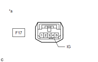
INSPECT SHIFT LOCK CONTROL UNIT ASSEMBLY (TRANSMISSION CONTROL SWITCH (POWER SOURCE)) |
|
(a) Disconnect the shift lock control unit assembly (transmission control switch) connector. |
|
(b) Measure the voltage according to the value(s) in the table below.
Standard Voltage:
|
Tester Connection |
Switch Condition |
Specified Condition |
|---|---|---|
|
F17-4 (IG) - Body ground |
Ignition switch ON |
11 to 14 V |
|
F17-4 (IG) - Body ground |
Ignition switch off |
Below 1 V |
| NG | |
CHECK POWER SOURCE CIRCUIT (TRANSMISSION CONTROL SWITCH) |
|
|
4. |
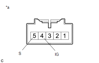
INSPECT SHIFT LOCK CONTROL UNIT ASSEMBLY (TRANSMISSION CONTROL SWITCH) |
|
(a) Disconnect the F17 shift lock control unit assembly (transmission control switch) connector. |
|
(b) Measure the resistance according to the value(s) in the table below.
Standard Resistance:
|
Tester Connection |
Condition |
Specified Condition |
|---|---|---|
|
4 (IG) - 5 (S) |
Shift lever in M, "+" or "-" |
Below 1 Ω |
|
4 (IG) - 5 (S) |
Shift lever not in M, "+" or "-" |
10 kΩ or higher |
| NG | |
REPLACE SHIFT LOCK CONTROL UNIT ASSEMBLY |
|
|
5. |
CHECK HARNESS AND CONNECTOR (SHIFT LOCK CONTROL UNIT ASSEMBLY (TRANSMISSION CONTROL SWITCH) - ECM) |
(a) Disconnect the F17 shift lock control unit assembly (transmission control switch) connector.
(b) Disconnect the A38 ECM connector.
(c) Measure the resistance according to the value(s) in the table below.
Standard Resistance:
|
Tester Connection |
Condition |
Specified Condition |
|---|---|---|
|
F17-5 (S) - A38-59 (S) |
Always |
Below 1 Ω |
|
F17-5 (S) - Body ground |
Always |
10 kΩ or higher |
|
A38-59 (S) - Body ground |
Always |
10 kΩ or higher |
| NG | |
REPAIR OR REPLACE HARNESS OR CONNECTOR (SHIFT LOCK CONTROL UNIT ASSEMBLY (TRANSMISSION CONTROL SWITCH) - ECM) |
|
|
6. |
REPLACE ECM |
(a) Replace the ECM.
Click here
| NEXT | |
PERFORM INITIALIZATION
|
|
7. |
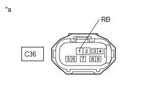
CHECK HARNESS AND CONNECTOR (BATTERY - PARK/NEUTRAL POSITION SWITCH) |
|
(a) Disconnect the park/neutral position switch connector. |
|
(b) Measure the voltage according to the value(s) in the table below.
Standard Voltage:
|
Tester Connection |
Switch Condition |
Specified Condition |
|---|---|---|
|
C36-1 (RB) - Body ground |
Ignition switch ON |
11 to 14 V |
|
C36-1 (RB) - Body ground |
Ignition switch off |
Below 1 V |
| NG | |
REPAIR OR REPLACE HARNESS OR CONNECTOR (BATTERY - PARK/NEUTRAL POSITION SWITCH) |
|
|
8. |
INSPECT PARK/NEUTRAL POSITION SWITCH |
|
(a) Disconnect the C36 park/neutral position switch connector. |
|
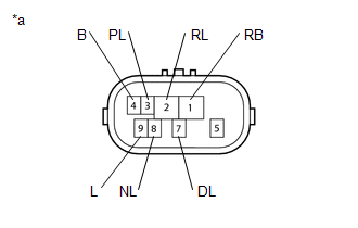
(b) Measure the resistance according to the value(s) in the table below.
Standard Resistance:
|
Tester Connection |
Condition |
Specified Condition |
|---|---|---|
|
4 (B) - 9 (L) |
Shift lever in P or N |
Below 1 Ω |
|
Shift lever not in P or N |
10 kΩ or higher |
|
|
1 (RB) - 3 (PL) |
Shift lever in P |
Below 1 Ω |
|
Shift lever not in P |
10 kΩ or higher |
|
|
1 (RB) - 2 (RL) |
Shift lever in R |
Below 1 Ω |
|
Shift lever not in R |
10 kΩ or higher |
|
|
1 (RB) - 8 (NL) |
Shift lever in N |
Below 1 Ω |
|
Shift lever not in N |
10 kΩ or higher |
|
|
1 (RB) - 7 (DL) |
Shift lever in D or M |
Below 1 Ω |
|
Shift lever not in D or M |
10 kΩ or higher |
| NG | |
REPLACE PARK/NEUTRAL POSITION SWITCH |
|
|
9. |
CHECK HARNESS AND CONNECTOR (PARK/NEUTRAL POSITION SWITCH - ECM) |
(a) Disconnect the C36 park/neutral position switch connector.
(b) Disconnect the C63 and A38 ECM connectors.
(c) Measure the resistance according to the value(s) in the table below.
Standard Resistance:
|
Tester Connection |
Condition |
Specified Condition |
|---|---|---|
|
C36-3 (PL) - C63-70 (P) |
Always |
Below 1 Ω |
|
C36-2 (RL) - C63-64 (R) |
Always |
Below 1 Ω |
|
C36-8 (NL) - C63-69 (N) |
Always |
Below 1 Ω |
|
C36-7 (DL) - C63-65 (D) |
Always |
Below 1 Ω |
|
C36-4 (B) - A38-23 (NSW) |
Always |
Below 1 Ω |
|
C36-3 (PL) or C63-70 (P) - Body ground and other terminals |
Always |
10 kΩ or higher |
|
C36-2 (RL) or C63-64 (R) - Body ground and other terminals |
Always |
10 kΩ or higher |
|
C36-8 (NL) or C63-69 (N) - Body ground and other terminals |
Always |
10 kΩ or higher |
|
C36-7 (DL) or C63-65 (D) - Body ground and other terminals |
Always |
10 kΩ or higher |
|
C36-4 (B) or A38-23 (NSW) - Body ground and other terminals |
Always |
10 kΩ or higher |
| OK | |
GO TO STEP 6 |
| NG | |
REPAIR OR REPLACE HARNESS OR CONNECTOR (PARK/NEUTRAL POSITION SWITCH - ECM) |
 Torque Converter Clutch Pressure Control Solenoid Control Circuit Electrical
(P2759)
Torque Converter Clutch Pressure Control Solenoid Control Circuit Electrical
(P2759)
DESCRIPTION
The ECM uses the shift solenoid valve SLU to perform forward and reverse clutch
control or lock-up clutch control.
*1
Spool Valve
*2
Sleev ...
 Transmission Fluid Temperature Sensor Circuit Range / Performance (P0711)
DESCRIPTION
The CVT fluid temperature sensor converts the fluid temperature into a resistance
value which is detected by the ECM.
The sensor resistance changes with the CVT fluid temperature. As t ...
Other materials:
Toyota CH-R Service Manual > Navigation Ecu: Components
COMPONENTS
ILLUSTRATION
*1
COWL SIDE TRIM BOARD LH
*2
FRONT DOOR SCUFF PLATE LH
*3
INSTRUMENT CLUSTER FINISH LOWER CENTER PANEL SUB-ASSEMBLY
*4
INSTRUMENT CLUSTER FINISH PANEL GARNISH ASSEMBLY
...
Toyota CH-R Service Manual > Navigation System: Sound Signal Circuit between Radio Receiver and Stereo Jack Adapter
DESCRIPTION
The stereo jack adapter assembly sends the sound signal from an external device
to the radio and display receiver assembly via this circuit.
The sound signal that has been sent is amplified by the radio and display receiver
assembly and then is sent to the speakers.
If there is an ...
Toyota C-HR (AX20) 2023-2026 Owner's Manual
Toyota CH-R Owners Manual
- For safety and security
- Instrument cluster
- Operation of each component
- Driving
- Interior features
- Maintenance and care
- When trouble arises
- Vehicle specifications
- For owners
Toyota CH-R Service Manual
- Introduction
- Maintenance
- Audio / Video
- Cellular Communication
- Navigation / Multi Info Display
- Park Assist / Monitoring
- Brake (front)
- Brake (rear)
- Brake Control / Dynamic Control Systems
- Brake System (other)
- Parking Brake
- Axle And Differential
- Drive Shaft / Propeller Shaft
- K114 Cvt
- 3zr-fae Battery / Charging
- Networking
- Power Distribution
- Power Assist Systems
- Steering Column
- Steering Gear / Linkage
- Alignment / Handling Diagnosis
- Front Suspension
- Rear Suspension
- Tire / Wheel
- Tire Pressure Monitoring
- Door / Hatch
- Exterior Panels / Trim
- Horn
- Lighting (ext)
- Mirror (ext)
- Window / Glass
- Wiper / Washer
- Door Lock
- Heating / Air Conditioning
- Interior Panels / Trim
- Lighting (int)
- Meter / Gauge / Display
- Mirror (int)
- Power Outlets (int)
- Pre-collision
- Seat
- Seat Belt
- Supplemental Restraint Systems
- Theft Deterrent / Keyless Entry

0.0101