Toyota CH-R Service Manual: Torque Converter Clutch Pressure Control Solenoid Control Circuit Electrical (P2759)
DESCRIPTION
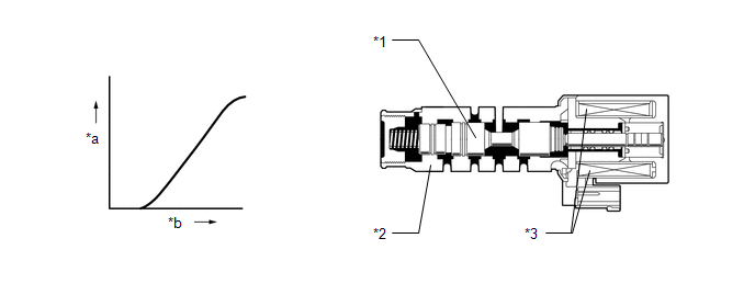
The ECM uses the shift solenoid valve SLU to perform forward and reverse clutch control or lock-up clutch control.
|
*1 |
Spool Valve |
*2 |
Sleeve |
|
*3 |
Solenoid Coil |
- |
- |
|
*a |
Hydraulic Pressure |
*b |
Current Flow to Solenoid |
|
DTC No. |
Detection Item |
DTC Detection Condition |
Trouble Area |
MIL |
Memory |
|---|---|---|---|---|---|
|
P2759 |
Torque Converter Clutch Pressure Control Solenoid Control Circuit Electrical |
While the vehicle is driven, there is an open or short in the shift solenoid valve SLU circuit for 1 second or more (1 trip detection logic). |
|
Comes on |
DTC stored |
MONITOR DESCRIPTION
This DTC indicates an open or short in the shift solenoid valve SLU circuit. If there is an open or short in the shift solenoid valve SLU circuit, the ECM detects the malfunction, illuminates the MIL and stores this DTC.
MONITOR STRATEGY
|
Related DTCs |
P2759: Torque Converter Clutch Pressure Control Solenoid (Shift solenoid valve SLU) / Range check |
|
Required sensors/Components |
Continuously variable transaxle assembly (Shift solenoid valve SLU) |
|
Frequency of operation |
Continuous |
|
Duration Conditions |
1 second |
|
MIL operation |
Immediately |
|
Sequence of operation |
None |
TYPICAL ENABLING CONDITIONS
All|
Solenoid current cut status |
Not cut |
|
Battery voltage |
8 V or more |
|
Time after Battery voltage 8 V or more |
0.5 seconds or more |
|
Write Inhibit |
permit |
|
Time after Write status forbiddance to permit |
0.5 seconds or more |
|
Ignition switch |
ON |
|
Time after Ignition switch OFF to ON |
0.5 seconds or more |
|
Starter |
OFF |
|
Time after Starter ON to OFF |
0.5 seconds or more |
|
One of the following conditions is met: |
- |
|
a. Battery voltage |
12 V or more |
|
b. All of the following conditions are met: |
- |
|
Battery voltage |
10 V or more and less than 12 V |
|
Target current |
Less than 0.75 A |
|
Target current |
0.25 A or more |
TYPICAL MALFUNCTION THRESHOLDS
Condition (A):|
Output duty cycle |
100% or more |
|
Output duty cycle |
0% or less |
COMPONENT OPERATING RANGE
|
Output duty cycle |
More than 0% and less than 100% |
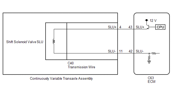
WIRING DIAGRAM
CAUTION / NOTICE / HINT
NOTICE:
- Perform initialization after replacing any parts related to the continuously
variable transaxle system.
Click here
.gif)
- Check that no DTCs are stored after performing initialization.
Click here
- Perform the universal trip to clear permanent DTCs.
Click here
HINT:
After performing repair, clear the DTCs and perform the following procedure to check that DTCs are not output.
- Drive the vehicle and confirm the lock-up on and off conditions according
to Road Test.
Click here
- Check for DTCs again.
Click here
PROCEDURE
|
1. |
INSPECT TRANSMISSION WIRE (SHIFT SOLENOID VALVE SLU) |
|
(a) Disconnect the C40 transmission wire connector. |
|
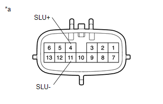
(b) Measure the resistance according to the value(s) in the table below.
Standard Resistance:
|
Tester Connection |
Condition |
Specified Condition |
|---|---|---|
|
4 (SLU+) - 11 (SLU-) |
20°C (68°F) |
5.0 to 5.6 Ω |
|
4 (SLU+) - Body ground and other terminals |
Always |
10 kΩ or higher |
|
11 (SLU-) - Body ground and other terminals |
Always |
10 kΩ or higher |
| NG | .gif) |
GO TO STEP 4 |
|
.gif)
|
2. |
CHECK HARNESS AND CONNECTOR (TRANSMISSION WIRE - ECM) |
|
(a) Disconnect the ECM connector. |
|
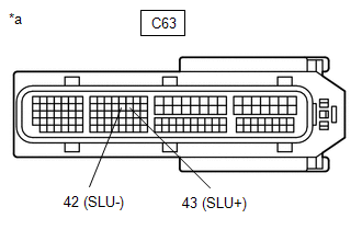
(b) Measure the resistance according to the value(s) in the table below.
Standard Resistance:
|
Tester Connection |
Condition |
Specified Condition |
|---|---|---|
|
C63-43 (SLU+) - C63-42 (SLU-) |
20°C (68°F) |
5.0 to 5.6 Ω |
|
C63-43 (SLU+) - Body ground and other terminals |
Always |
10 kΩ or higher |
|
C63-42 (SLU-) - Body ground and other terminals |
Always |
10 kΩ or higher |
| NG | |
REPAIR OR REPLACE HARNESS OR CONNECTOR (TRANSMISSION WIRE - ECM) |
|
|
3. |
REPLACE ECM |
(a) Replace the ECM.
Click here
| NEXT | |
PERFORM INITIALIZATION
|
|
4. |
REPLACE CONTINUOUSLY VARIABLE TRANSAXLE ASSEMBLY |
(a) Replace the continuously variable transaxle assembly.
- When Not Using the Engine Support Bridge
Click here
- When Using the Engine Support Bridge
Click here
| NEXT | |
PERFORM INITIALIZATION |
 Acceleration Sensor Learning Value (P1589)
DESCRIPTION
The ECM stores DTC P1589 if deceleration sensor zero point calibration is not
performed or failed after system components such as the ECM are replaced.
DTC No.
De ...
 Transmission Range Sensor Circuit (PRNDL Input) (P0705)
DESCRIPTION
The park/neutral position switch and transmission control switch (shift lock
control unit assembly) detect the shift lever position and send signals to the ECM.
DTC No.
...
Other materials:
Toyota CH-R Service Manual > Theft Deterrent System: Terminals Of Ecu
TERMINALS OF ECU
CHECK INSTRUMENT PANEL JUNCTION BLOCK ASSEMBLY AND MAIN BODY ECU (MULTIPLEX NETWORK
BODY ECU)
*A
Main Body ECU (Multiplex Network Body ECU) with 2 Connectors
-
-
*1
Main Body ECU (Multiplex Network Body EC ...
Toyota CH-R Service Manual > Steering Heater Switch: Inspection
INSPECTION
PROCEDURE
1. INSPECT STEERING HEATER SWITCH
(a) Check the resistance.
(1) Measure the resistance according to the value(s) in the table below.
Standard Resistance:
Tester Connection
Switch Condition
Specified Conditi ...
Toyota C-HR (AX20) 2023-2026 Owner's Manual
Toyota CH-R Owners Manual
- For safety and security
- Instrument cluster
- Operation of each component
- Driving
- Interior features
- Maintenance and care
- When trouble arises
- Vehicle specifications
- For owners
Toyota CH-R Service Manual
- Introduction
- Maintenance
- Audio / Video
- Cellular Communication
- Navigation / Multi Info Display
- Park Assist / Monitoring
- Brake (front)
- Brake (rear)
- Brake Control / Dynamic Control Systems
- Brake System (other)
- Parking Brake
- Axle And Differential
- Drive Shaft / Propeller Shaft
- K114 Cvt
- 3zr-fae Battery / Charging
- Networking
- Power Distribution
- Power Assist Systems
- Steering Column
- Steering Gear / Linkage
- Alignment / Handling Diagnosis
- Front Suspension
- Rear Suspension
- Tire / Wheel
- Tire Pressure Monitoring
- Door / Hatch
- Exterior Panels / Trim
- Horn
- Lighting (ext)
- Mirror (ext)
- Window / Glass
- Wiper / Washer
- Door Lock
- Heating / Air Conditioning
- Interior Panels / Trim
- Lighting (int)
- Meter / Gauge / Display
- Mirror (int)
- Power Outlets (int)
- Pre-collision
- Seat
- Seat Belt
- Supplemental Restraint Systems
- Theft Deterrent / Keyless Entry

0.0106