Toyota CH-R Service Manual: Installation
INSTALLATION
CAUTION / NOTICE / HINT
PROCEDURE
1. INSTALL TRANSMISSION BREATHER HOSE SUB-ASSEMBLY
HINT:
Perform this procedure only when replacement of the transmission breather hose sub-assembly is necessary.
(a) Apply Toyota Genuine CVT fluid FE to a new O-ring, and install it to the No. 2 breather plug (CVT).
NOTICE:
Be careful not to damage or twist the O-ring.
(b) Install the No. 1 breather plug (CVT) and No. 2 breather plug (CVT) to the breather plug hose.
(c) Install the transmission breather hose sub-assembly to the continuously variable transaxle assembly.
2. INSTALL STRAIGHT SCREW PLUG
HINT:
Perform this procedure only when replacement of the straight screw plug is necessary.
(a) Install a new gasket and the straight screw plug to the continuously variable transaxle assembly.
Torque:
16.2 N·m {165 kgf·cm, 12 ft·lbf}
3. INSTALL AUTOMATIC TRANSMISSION CASE COVER
(a) Install the automatic transmission case cover to the continuously variable transaxle assembly with the 2 clips.
4. INSTALL OIL COOLER ELBOW SUB-ASSEMBLY
(a) Install a new gasket and oil cooler elbow sub-assembly to the continuously variable transaxle assembly with the union bolt.
Torque:
22.6 N·m {230 kgf·cm, 17 ft·lbf}
NOTICE:
- Make sure to insert the painted end (white) of the No. 2 transmission oil cooler hose up to the spool fitting of the oil cooler elbow sub-assembly so that the marking is facing the front of the vehicle.
- Make sure to clean and degrease the insertion part of the No. 2 transmission oil cooler hose of the oil cooler elbow sub-assembly.
(b) Install the No. 2 transmission oil cooler hose to the oil cooler elbow sub-assembly and slide the clip to secure it.
5. INSTALL TUBE CONNECTOR
(a) Install a new O-ring to the tube connector.
(b) Install the tube connector to the continuously variable transaxle assembly.
Torque:
27 N·m {275 kgf·cm, 20 ft·lbf}
NOTICE:
- Make sure to insert the painted end (white) of the No. 1 transmission oil cooler hose up to the spool fitting of the tube connector so that the marking is facing the front of the vehicle.
- Make sure to clean and degrease the insertion part of the No. 1 transmission oil cooler hose of the tube connector.
(c) Install the No. 1 transmission oil cooler hose to the tube connector and slide the clip to secure it.
6. INSTALL WIRE HARNESS CLAMP BRACKET
|
(a) Install the 3 wire harness clamp brackets to the continuously variable transaxle assembly with the 3 bolts. Torque: 8.0 N·m {82 kgf·cm, 71 in·lbf} |
|
.png)
(b) Install the water by-pass hose clamp to the water hose clamp bracket.
(c) Install the water hose clamp bracket to the continuously variable transaxle assembly with the bolt.
Torque:
10 N·m {102 kgf·cm, 7 ft·lbf}
7. INSTALL TRANSMISSION CONTROL CABLE SUPPORT
(a) Install the transmission control cable support to the continuously variable transaxle assembly with the 2 bolts.
Torque:
8.0 N·m {82 kgf·cm, 71 in·lbf}
8. INSTALL CVT OIL PUMP TYPE T OIL SEAL
(a) Ensure that there is no dirt or foreign matter on your hands, and then apply MP grease to the entire periphery of the lip of a new CVT oil pump type T oil seal.
(b) Temporarily install the CVT oil pump type T oil seal by pressing it to the installation surface of the oil pump housing manually.
NOTICE:
Be sure to install the CVT oil pump type T oil seal in the correct direction.
(c) Clean the CVT oil pump type T oil seal contact surface of SST and the area around it.
SST: 09309-36010
|
(d) Using SST, drive the CVT oil pump type T oil seal in evenly, until it is even with the side surface of the oil pump housing. Standard depth: 0 to 0.5 mm (0 to 0.0196 in.) NOTICE:
HINT: The CVT oil pump type T oil seal should be driven in between 0 to 0.5 mm (0 to 0.0196 in.) as measured from the side surface of the oil pump housing. |
|
.png)
9. INSTALL TORQUE CONVERTER ASSEMBLY
|
(a) Turn the front oil pump drive gear so that the wide groove is at the top and place a matchmark on the transaxle housing. NOTICE: Align the matchmark with the wide groove of the transaxle housing. |
|
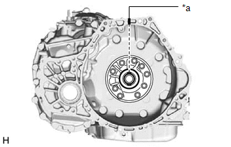
|
(b) Place a matchmark on the torque converter assembly so that the position of its key is clearly indicated. |
|
.png)
|
(c) Align the matchmark on the transaxle housing with the one on the torque converter assembly and engage the splines of the input shaft with the turbine runner splines. NOTICE:
|
|
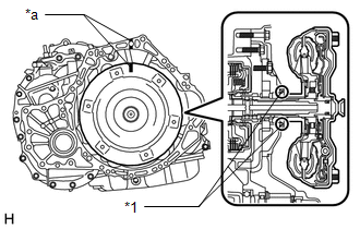
|
(d) Rotate the torque converter assembly approximately 180° and engage the splines of the stator shaft with the stator assembly. NOTICE:
|
|
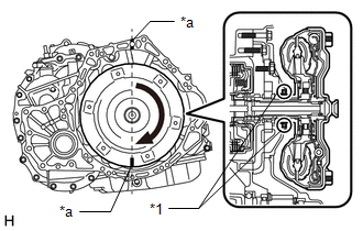
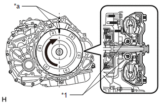
|
(e) Rotate the torque converter assembly approximately 180° again, align the matchmark on the torque converter assembly with the one on the transaxle housing and insert the key of the torque converter assembly into the groove of the oil pump drive gear. NOTICE:
|
|
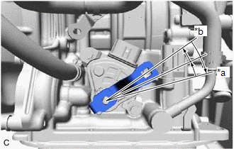
(f) Clean the drive plate and torque converter assembly setting bolt holes.
|
(g) Using a vernier caliper and straightedge, measure the dimension (A) between the continuously variable transaxle assembly contact surface of the engine assembly*a and the torque converter assembly contact surfaces of the drive plate*b. |
|
.png)
|
(h) Using a vernier caliper and straightedge, measure the dimension (B) shown in the illustration and check that the dimension (B) is more than the dimension (A), which was measured in the previous step. Standard: B = A + 1 mm (0.0394 in.) or more NOTICE:
|
|
.png)
10. SUPPORT CONTINUOUSLY VARIABLE TRANSAXLE ASSEMBLY
(a) Using a transmission jack, support the continuously variable transaxle assembly.
NOTICE:
- Adjust the attachment of the transmission jack to securely fix the continuously variable transaxle assembly to the transmission jack.
- To prevent the transaxle oil (CVT) pan sub-assembly from deforming, do not place any attachments under the transaxle oil (CVT) pan sub-assembly of the continuously variable transaxle assembly.
- Using a lashing belt or a rope, fix the continuously variable transaxle assembly to the transmission jack.
11. INSTALL CONTINUOUSLY VARIABLE TRANSAXLE ASSEMBLY
|
(a) Apply clutch spline grease to the surface of the crankshaft that contacts the torque converter assembly centerpiece. Clutch spline grease: Toyota Genuine Clutch Spline Grease or equivalent Maximum grease amount: Approximately 1 g (0.0353 oz.) |
|
.png)
|
(b) Confirm that the 2 knock pins are installed to the engine assembly and are not damaged. |
|
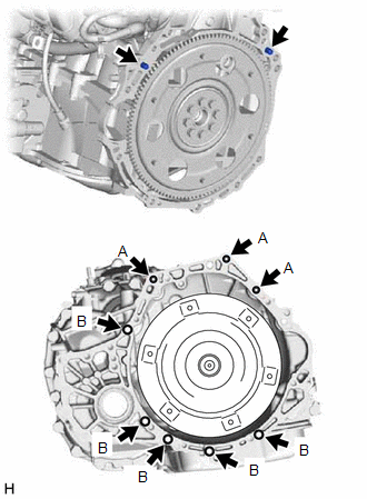
(c) Install the continuously variable transaxle assembly to the engine assembly with the 8 bolts.
Torque:
Bolt (A) :
38 N·m {387 kgf·cm, 28 ft·lbf}
Bolt (B) :
40 N·m {408 kgf·cm, 30 ft·lbf}
NOTICE:
- Make sure that the wire harness or similar items are not pinched between the contact surfaces.
- Do not use excess force when installing the continuously variable transaxle assembly.
- When mounting the continuously variable transaxle assembly to the engine assembly, make sure to securely fit the 2 knock pins into the knock holes.
- Check that the torque converter assembly rotates.
- When tightening the bolts, be sure that the mating surfaces of the engine assembly and the continuously variable transaxle assembly are in close contact with one another.
HINT:
- Bolt (A): Install from continuously variable transaxle assembly side
- Bolt (B): Install from engine assembly side
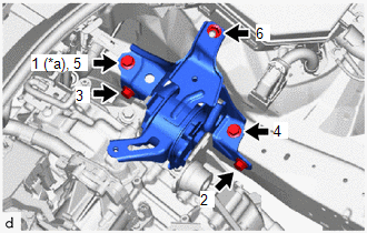
12. INSTALL TRANSVERSE ENGINE ENGINE MOUNTING BRACKET
|
(a) Install the transverse engine engine mounting bracket with the 5 new bolts. Torque: 41 N·m {418 kgf·cm, 30 ft·lbf} |
|
.png)
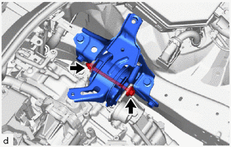
13. INSTALL TRANSVERSE ENGINE ENGINE MOUNTING INSULATOR
|
(a) Temporarily install the transverse engine engine mounting insulator to the vehicle body with the nut and 4 bolts. |
|
(b) Fully tighten the nut and 4 bolts in the order shown in the illustration.
Torque:
42 N·m {428 kgf·cm, 31 ft·lbf}
|
(c) Install the transverse engine engine mounting insulator to the transverse engine engine mounting bracket with the bolt and nut. Torque: 44 N·m {449 kgf·cm, 32 ft·lbf} NOTICE: Turn the bolt while holding the nut. |
|
14. INSTALL DRIVE PLATE AND TORQUE CONVERTER ASSEMBLY SETTING BOLT
(a) Using SST, hold the crankshaft pulley.
SST: 09213-54015
SST: 09330-00021
HINT:
Part number of installation bolt for SST (crankshaft pulley holding tool): 91551-00850 (quantity: 2)
(b) Clean the threads of the 6 drive plate and torque converter assembly setting bolts.
|
(c) Apply a few drops of adhesive to 2 or 3 threads at the tip of each of the 6 drive plate and torque converter assembly setting bolts. Adhesive: Toyota Genuine Adhesive 1324, Three Bond 1324 or equivalent NOTICE: In order to ensure proper installation of the 6 drive plate and torque converter assembly setting bolts, apply adhesive to the 6 drive plate and torque converter assembly setting bolts and install them within 10 minutes of adhesive application. |
|
.png)
(d) Turn the crankshaft to gain access to the installation locations of the 6 drive plate and torque converter assembly setting bolts and install each bolt while holding the crankshaft pulley with SST.
Torque:
41 N·m {418 kgf·cm, 30 ft·lbf}
NOTICE:
First install the black-colored bolt, and then the remaining 5 silver-colored bolts.
15. INSTALL FLYWHEEL HOUSING UNDER COVER
(a) Install the flywheel housing under cover.
16. INSTALL FLYWHEEL HOUSING SIDE COVER
Click here
.gif)
17. INSTALL STARTER ASSEMBLY
Click here
18. INSTALL NO. 2 ENGINE MOVING CONTROL ROD
|
(a) Install the No. 2 engine moving control rod to the continuously variable transaxle assembly with the 4 bolts in the order shown in the illustration. Torque: 44 N·m {449 kgf·cm, 32 ft·lbf} |
|
.png)
19. INSTALL FRONT SUSPENSION CROSSMEMBER SUB-ASSEMBLY
Click here
20. INSTALL REAR SIDE RAIL REINFORCEMENT SUB-ASSEMBLY LH
Click here
21. INSTALL REAR SIDE RAIL REINFORCEMENT SUB-ASSEMBLY RH
Click here
22. REMOVE ENGINE SUPPORT BRIDGE
(a) Remove SST from the vehicle body.
NOTICE:
Prevent SST from contacting the vehicle body or windshield glass.
(b) Install the neck from the windshield washer jar assembly with the clip.
23. REMOVE ENGINE HANGER
(a) Remove the 2 bolts and No. 2 engine hanger from the cylinder head.
(b) Remove the 2 bolts and No. 1 engine hanger from the cylinder head.
|
(c) Install the wire harness clamp bracket with the bolt. Torque: 39 N·m {398 kgf·cm, 29 ft·lbf} |
|
(d) Connect the air fuel ratio sensor connector.
(e) Engage the 5 clamps.
24. INSTALL FRONT DRIVE SHAFT ASSEMBLIES
Click here
25. INSTALL FRONT EXHAUST PIPE ASSEMBLY (TWC: Front and Rear Catalyst)
Click here
26. INSTALL FRONT FLOOR CENTER BRACE
Click here
27. INSTALL FRONT FLOOR COVER LH (w/ Cover)
Click here
28. INSTALL FRONT FLOOR COVER RH (w/ Cover)
HINT:
Use the same procedure as for the LH side.
29. INSTALL NO. 1 STEERING COLUMN HOLE COVER SUB-ASSEMBLY
Click here
30. ALIGN FRONT WHEELS FACING STRAIGHT AHEAD
31. CONNECT NO. 2 STEERING INTERMEDIATE SHAFT ASSEMBLY
Click here
32. INSTALL COLUMN HOLE COVER SILENCER SHEET
Click here
33. INSTALL NO. 1 TRANSMISSION CONTROL CABLE BRACKET
(a) Install the No. 1 transmission control cable bracket to the continuously variable transaxle assembly with the 2 bolts.
Torque:
12 N·m {122 kgf·cm, 9 ft·lbf}
(b) Connect the clamp to the No. 1 transmission control cable bracket.
34. CONNECT ENGINE WIRE
(a) Engage the 5 clamps to connect the engine wire to the continuously variable transaxle assembly.
.png)
|
*1 |
Park/Neutral Position Switch Connector |
*2 |
Transmission Wire Connector |
|
*3 |
Transmission Revolution Sensor (NIN) Connector |
*4 |
Transmission Revolution Sensor (NOUT) Connector |
|
*5 |
Transmission Revolution Sensor (NT) Connector |
*6 |
Oil Pressure Sensor Connector |
(b) Connect the engine wire to the continuously variable transaxle assembly with the 3 bolts and nut.
Torque:
Bolt (A) :
8.5 N·m {87 kgf·cm, 75 in·lbf}
Bolt (B) :
8.0 N·m {82 kgf·cm, 71 in·lbf}
Nut :
8.0 N·m {82 kgf·cm, 71 in·lbf}
(c) Connect the oil pressure sensor connector.
(d) Connect the transmission revolution sensor (NOUT) connector.
(e) Connect the transmission revolution sensor (NIN) connector.
(f) Connect the transmission revolution sensor (NT) connector.
(g) Connect the transmission wire connector.
(h) Connect the park/neutral position switch connector.
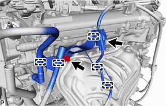
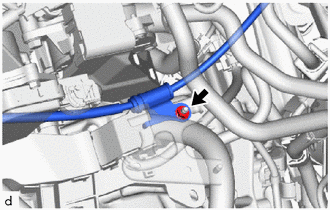
35. CONNECT NO. 3 WATER BY-PASS HOSE
(a) Connect the No. 3 water by-pass hose to the oil cooler, and slide the clip to secure it.
NOTICE:
- Align each paint mark on the No. 3 water by-pass hose with each one on the oil cooler.
- Fully insert the No. 3 water by-pass hose to the 2nd rib on each oil cooler pipe.
36. CONNECT NO. 5 WATER BY-PASS HOSE
(a) Connect the No. 5 water by-pass hose to the oil cooler, and slide the clip to secure it.
NOTICE:
- Align each paint mark on the No. 5 water by-pass hose with each one on the oil cooler.
- Fully insert the No. 5 water by-pass hose to the 2nd rib on each oil cooler pipe.
37. CONNECT TRANSMISSION CONTROL CABLE ASSEMBLY
|
(a) Install the transmission control cable assembly to the transmission control cable support with the nut. Torque: 5.0 N·m {51 kgf·cm, 44 in·lbf} |
|
|
(b) Turn the control shaft lever clockwise until it stops, then turn it counterclockwise 2 notches. |
|
(c) Install the transmission control cable assembly to the No. 1 transmission control cable bracket with a new clip.
(d) Connect the transmission control cable assembly to the control shaft lever with the nut.
Torque:
12 N·m {122 kgf·cm, 9 ft·lbf}
38. INSTALL BATTERY CLAMP SUB-ASSEMBLY
(a) Install the air battery clamp sub-assembly to the vehicle with the 3 bolts.
Torque:
15.4 N·m {157 kgf·cm, 11 ft·lbf}
(b) Engage the clamp to connect the engine wire to the battery clamp sub-assembly.
(c) Connect the engine wire to the battery clamp sub-assembly with the bolt and nut.
Torque:
7.0 N·m {71 kgf·cm, 62 in·lbf}
39. INSTALL ECM
Click here
40. INSTALL AIR CLEANER CASE SUB-ASSEMBLY
Click here
41. INSTALL AIR CLEANER CAP WITH AIR CLEANER HOSE
Click here
42. INSTALL NO. 1 AIR CLEANER INLET
Click here
43. INSTALL RADIATOR COVER
Click here
44. INSTALL OUTER COWL TOP PANEL SUB-ASSEMBLY
Click here
45. INSTALL COWL BODY MOUNTING REINFORCEMENT RH
Click here
46. INSTALL COWL BODY MOUNTING REINFORCEMENT LH
Click here
47. INSTALL WATER GUARD PLATE LH
Click here
48. INSTALL NO. 1 HEATER AIR DUCT SPLASH SHIELD SEAL
Click here
49. INSTALL WINDSHIELD WIPER MOTOR AND LINK
Click here
50. INSTALL FRONT WHEELS
Click here
51. INSTALL BATTERY
Click here
52. CONNECT CABLE TO NEGATIVE BATTERY TERMINAL
Click here
NOTICE:
When disconnecting the cable, some systems need to be initialized after the cable is reconnected.
Click here
53. ADD ENGINE COOLANT
Click here
54. ADD CONTINUOUSLY VARIABLE TRANSAXLE FLUID
Click here
55. INSPECT FOR COOLANT LEAK
Click here
56. INSPECT FOR CONTINUOUSLY VARIABLE TRANSAXLE FLUID LEAK
57. INSPECT FOR EXHAUST GAS LEAK
Click here
HINT:
Perform "Inspection After Repairs" after repairing or replacing the exhaust system.
Click here
58. INSPECT SHIFT LEVER POSITION
Click here
59. ADJUST SHIFT LEVER POSITION
Click here
60. INSTALL REAR ENGINE UNDER COVER RH
Click here
61. INSTALL REAR ENGINE UNDER COVER LH
Click here
62. INSTALL NO. 1 ENGINE UNDER COVER
Click here
63. INSTALL NO. 2 CYLINDER HEAD COVER
Click here
64. CHECK FOR SPEED SENSOR SIGNAL
Click here
65. INSPECT AND ADJUST FRONT WHEEL ALIGNMENT
Click here
66. RESET MEMORY
Click here
 Components
COMPONENTS
ILLUSTRATION
*1
NO. 1 ENGINE UNDER COVER
*2
REAR ENGINE UNDER COVER LH
*3
REAR ENGINE UNDER COVER RH
- ...
 Removal
REMOVAL
CAUTION / NOTICE / HINT
The necessary procedures (adjustment, calibration, initialization, or registration)
that must be performed after parts are removed, installed, or replaced during th ...
Other materials:
Toyota CH-R Service Manual > Occupant Classification System: System Diagram
SYSTEM DIAGRAM
Communication Table
Transmitting ECU
(Transmitter)
Receiving ECU
Signal
Communication Method
Airbag Sensor Assembly
Occupant Detection ECU
Crash detection signal
Acceleration sign ...
Toyota CH-R Service Manual > Meter / Gauge System: Customize Parameters
CUSTOMIZE PARAMETERS
CUSTOMIZE METER / GAUGE SYSTEM
(a) Customizing with the Techstream.
(1) Connect the Techstream to the DLC3.
(2) Turn the ignition switch ON.
(3) Turn the Techstream on.
(4) Enter the following menus: Customize Setting / Warning or Display.
(5) Select the setting by referr ...
Toyota C-HR (AX20) 2023-2026 Owner's Manual
Toyota CH-R Owners Manual
- For safety and security
- Instrument cluster
- Operation of each component
- Driving
- Interior features
- Maintenance and care
- When trouble arises
- Vehicle specifications
- For owners
Toyota CH-R Service Manual
- Introduction
- Maintenance
- Audio / Video
- Cellular Communication
- Navigation / Multi Info Display
- Park Assist / Monitoring
- Brake (front)
- Brake (rear)
- Brake Control / Dynamic Control Systems
- Brake System (other)
- Parking Brake
- Axle And Differential
- Drive Shaft / Propeller Shaft
- K114 Cvt
- 3zr-fae Battery / Charging
- Networking
- Power Distribution
- Power Assist Systems
- Steering Column
- Steering Gear / Linkage
- Alignment / Handling Diagnosis
- Front Suspension
- Rear Suspension
- Tire / Wheel
- Tire Pressure Monitoring
- Door / Hatch
- Exterior Panels / Trim
- Horn
- Lighting (ext)
- Mirror (ext)
- Window / Glass
- Wiper / Washer
- Door Lock
- Heating / Air Conditioning
- Interior Panels / Trim
- Lighting (int)
- Meter / Gauge / Display
- Mirror (int)
- Power Outlets (int)
- Pre-collision
- Seat
- Seat Belt
- Supplemental Restraint Systems
- Theft Deterrent / Keyless Entry

0.0092