Toyota CH-R Service Manual: Removal
REMOVAL
CAUTION / NOTICE / HINT
The necessary procedures (adjustment, calibration, initialization or registration) that must be performed after parts are removed and installed, or replaced during the black out tape removal/installation are shown below.
Necessary Procedure After Parts Removed/Installed/Replaced|
Replaced Part or Performed Procedure |
Necessary Procedure |
Effect/Inoperative Function when Necessary Procedure not Performed |
Link |
|---|---|---|---|
|
Disconnect cable from negative battery terminal |
Initialize back door lock |
Power door lock control system |
|
|
Memorize steering angle neutral point |
Lane departure alert system (w/ Steering Control) |
|
|
|
Pre-collision system |
|||
|
Initialize Power Window Control System |
|
|
HINT:
- Use the same procedure for the RH side and LH side.
- The following procedure is for the LH side.
PROCEDURE
1. PRECAUTION
NOTICE:
After turning the ignition switch off, waiting time may be required before disconnecting the cable from the negative (-) battery terminal. Therefore, make sure to read the disconnecting the cable from the negative (-) battery terminal notices before proceeding with work.
Click here
.gif)
2. DISCONNECT CABLE FROM NEGATIVE BATTERY TERMINAL
Click here
NOTICE:
When disconnecting the cable, some systems need to be initialized after the cable is reconnected.
Click here
3. REMOVE FRONT DOOR INSIDE HANDLE BEZEL PLUG
Click here
4. REMOVE MULTIPLEX NETWORK MASTER SWITCH ASSEMBLY WITH FRONT ARMREST BASE UPPER PANEL (for Driver Side)
Click here
5. REMOVE POWER WINDOW REGULATOR SWITCH ASSEMBLY WITH FRONT ARMREST BASE UPPER PANEL (for Front Passenger Side)
Click here
6. REMOVE FRONT DOOR TRIM BOARD SUB-ASSEMBLY
Click here
7. REMOVE FRONT DOOR LOWER FRAME BRACKET GARNISH
Click here
8. DISCONNECT FRONT DOOR WEATHERSTRIP
Click here
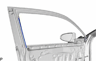
9. REMOVE FRONT DOOR BELT SEAL
Click here
10. REMOVE FRONT DOOR GLASS INNER WEATHERSTRIP
Click here
11. REMOVE FRONT DOOR VENT SEAL
Click here
12. REMOVE OUTER REAR VIEW MIRROR ASSEMBLY
Click here
13. REMOVE FRONT DOOR SERVICE HOLE COVER
Click here
14. REMOVE FRONT DOOR GLASS SUB-ASSEMBLY
Click here
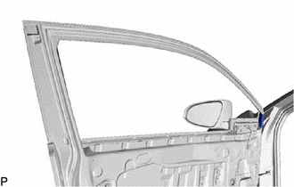
15. REMOVE DOOR FRAME UPPER GARNISH
Click here
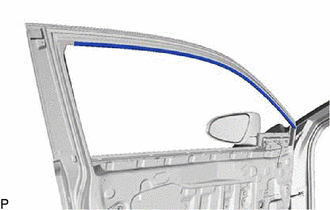
16. REMOVE FRONT DOOR GLASS RUN
Click here
17. REMOVE FRONT DOOR FRONT LOWER FRAME SUB-ASSEMBLY
Click here
18. REMOVE FRONT DOOR FIX WINDOW GLASS
Click here
19. REMOVE NO. 4 FRONT DOOR STRIPE
HINT:
When removing the No. 4 front door stripe, heat the vehicle body and No. 4 front door stripe using a heat light.
Heating Temperature|
Item |
Temperature |
|---|---|
|
No. 4 Front Door Stripe and Vehicle Body |
40 to 60°C (104 to 140°F) |
CAUTION:
- Do not touch the heat light and heated parts, touching the heat light may result in burns.
- Touching heated parts for a long time may result in burns.
.png)
|
*a |
Heated Part |
|
*b |
Heat Light |
NOTICE:
Do not heat the vehicle body excessively.
(a) Using a heat light, heat the No. 4 front door stripe and vehicle body.
|
(b) Pull back on one of the ends of the No. 4 front door stripe to remove it. HINT: When pulling on the No. 4 front door stripe, pull it parallel to the vehicle body. |
|
20. REMOVE FRONT DOOR OUTSIDE STRIPE
HINT:
When removing the front door outside stripe, heat the vehicle body and front door outside stripe using a heat light.
Heating Temperature|
Item |
Temperature |
|---|---|
|
Front Door Outside Stripe and Vehicle Body |
40 to 60°C (104 to 140°F) |
CAUTION:
- Do not touch the heat light and heated parts, touching the heat light may result in burns.
- Touching heated parts for a long time may result in burns.
|
*a |
Heated Part |
|
*b |
Heat Light |
NOTICE:
Do not heat the vehicle body excessively.
(a) Using a heat light, heat the front door outside stripe and vehicle body.
|
(b) Pull back on one of the ends of the front door outside stripe to remove it. HINT: When pulling on the front door outside stripe, pull it parallel to the vehicle body. |
|
21. REMOVE NO. 2 FRONT DOOR STRIPE
HINT:
When removing the No. 2 front door stripe, heat the vehicle body and No. 2 front door stripe using a heat light.
Heating Temperature|
Item |
Temperature |
|---|---|
|
No. 2 Front Door Stripe and Vehicle Body |
40 to 60°C (104 to 140°F) |
CAUTION:
- Do not touch the heat light and heated parts, touching the heat light may result in burns.
- Touching heated parts for a long time may result in burns.
|
*a |
Heated Part |
|
*b |
Heat Light |
NOTICE:
Do not heat the vehicle body excessively.
(a) Using a heat light, heat the No. 2 front door stripe and vehicle body.
|
(b) Pull back on one of the ends of the No. 2 front door stripe to remove it. HINT: When pulling on the No. 2 front door stripe, pull it parallel to the vehicle body. |
|
 Components
COMPONENTS
ILLUSTRATION
*A
for Driver Side
*B
for Front Passenger Side
*1
FRONT DOOR INSIDE HANDLE BEZEL PLUG
*2
...
 Installation
INSTALLATION
CAUTION / NOTICE / HINT
HINT:
Use the same procedure for the RH side and LH side.
The following procedure is for the LH side.
PROCEDURE
1. REPAIR INSTRUCTION
(a) C ...
Other materials:
Toyota CH-R Service Manual > Smart Key System(for Start Function): Brake Signal Malfunction (B2284)
DESCRIPTION
This DTC is stored when the brake signal sent via direct line and the brake signal
sent via CAN communication do not match.
DTC No.
Detection Item
DTC Detection Condition
Trouble Area
Note
B2284
Brake ...
Toyota CH-R Service Manual > Navigation System: Route cannot be Calculated
PROCEDURE
1.
SET DESTINATION
(a) Set another destination and check if the system can calculate the route correctly.
OK:
Route can be correctly calculated.
OK
END
NG
PROCEED TO NEXT SUSPECTED AREA SHOWN IN PROBLEM S ...
Toyota C-HR (AX20) 2023-2026 Owner's Manual
Toyota CH-R Owners Manual
- For safety and security
- Instrument cluster
- Operation of each component
- Driving
- Interior features
- Maintenance and care
- When trouble arises
- Vehicle specifications
- For owners
Toyota CH-R Service Manual
- Introduction
- Maintenance
- Audio / Video
- Cellular Communication
- Navigation / Multi Info Display
- Park Assist / Monitoring
- Brake (front)
- Brake (rear)
- Brake Control / Dynamic Control Systems
- Brake System (other)
- Parking Brake
- Axle And Differential
- Drive Shaft / Propeller Shaft
- K114 Cvt
- 3zr-fae Battery / Charging
- Networking
- Power Distribution
- Power Assist Systems
- Steering Column
- Steering Gear / Linkage
- Alignment / Handling Diagnosis
- Front Suspension
- Rear Suspension
- Tire / Wheel
- Tire Pressure Monitoring
- Door / Hatch
- Exterior Panels / Trim
- Horn
- Lighting (ext)
- Mirror (ext)
- Window / Glass
- Wiper / Washer
- Door Lock
- Heating / Air Conditioning
- Interior Panels / Trim
- Lighting (int)
- Meter / Gauge / Display
- Mirror (int)
- Power Outlets (int)
- Pre-collision
- Seat
- Seat Belt
- Supplemental Restraint Systems
- Theft Deterrent / Keyless Entry

0.0087