Toyota CH-R Service Manual: Brake Signal Malfunction (B2284)
DESCRIPTION
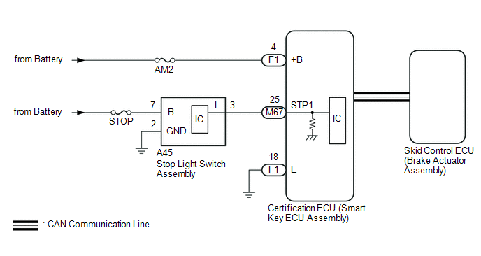
This DTC is stored when the brake signal sent via direct line and the brake signal sent via CAN communication do not match.
|
DTC No. |
Detection Item |
DTC Detection Condition |
Trouble Area |
Note |
|---|---|---|---|---|
|
B2284 |
Brake Signal Malfunction |
The brake signal sent via direct line and the brake signal sent via CAN communication do not match. (1-trip detection logic*) |
|
|
- *: Only detected while a malfunction is present and the engine switch is on (IG).
|
Vehicle Condition when Malfunction Detected |
Fail-safe Function when Malfunction Detected |
|---|---|
|
With the electrical key transmitter sub-assembly in the cabin, even if an engine start operation is performed, the engine does not start (the key indicator display is not displayed on the multi-information display). However, the engine can be started by turning the engine switch on (ACC) and then pressing and holding it.
|
- |
|
DTC No. |
Data List and Active Test |
|---|---|
|
B2284 |
Power Source Control
ABS/VSC/TRC/EPB
|
WIRING DIAGRAM
CAUTION / NOTICE / HINT
NOTICE:
- When using the Techstream with the engine switch off, connect the Techstream to the DLC3 and turn a courtesy light switch on and off at intervals of 1.5 seconds or less until communication between the Techstream and the vehicle begins. Then select the vehicle type under manual mode and enter the following menus: Body Electrical / Smart Key. While using the Techstream, periodically turn a courtesy light switch on and off at intervals of 1.5 seconds or less to maintain communication between the Techstream and the vehicle.
- The smart key system (for Start Function) uses the LIN communication
system and CAN communication system. Inspect the communication function
by following How to Proceed with Troubleshooting. Troubleshoot the smart
key system (for Start Function) after confirming that the communication
systems are functioning properly.
Click here
.gif)
- Inspect the fuses of circuits related to this system before performing the following procedure.
- Before replacing the certification ECU (smart key ECU assembly), refer
to smart key system (for Start Function) Precaution.
Click here
- After repair, confirm that no DTCs are output by performing "DTC Output Confirmation Operation".
HINT:
When the cable is disconnected and reconnected to the negative (-) battery terminal, the power source mode returns to the state it was in before the cable was disconnected.
PROCEDURE
|
1. |
READ VALUE USING TECHSTREAM (STOP LIGHT SWITCH1) |
(a) Connect the Techstream to the DLC3.
(b) Turn the engine switch on (IG).
(c) Turn the Techstream on.
(d) Enter the following menus: Body Electrical / Power Source Control / Data List.
(e) Read the Data List according to the display on the Techstream.
Body Electrical > Power Source Control > Data List|
Tester Display |
Measurement Item |
Range |
Normal Condition |
Diagnostic Note |
|---|---|---|---|---|
|
Stop Light Switch1 |
State of brake pedal |
OFF or ON |
OFF: Brake pedal released ON: Brake pedal depressed |
|
|
Tester Display |
|---|
|
Stop Light Switch1 |
OK:
The Techstream display changes correctly in response to the brake pedal operation.
| OK | .gif) |
GO TO VEHICLE STABILITY CONTROL SYSTEM (HOW TO PROCEED WITH TROUBLESHOOTING) |
|
.gif)
|
2. |
CHECK HARNESS AND CONNECTOR (POWER SOURCE) |
Click here
| NG | |
REPAIR OR REPLACE HARNESS OR CONNECTOR IN CIRCUIT CONNECTED TO POWER SOURCE |
|
|
3. |
CHECK HARNESS AND CONNECTOR (GROUND) |
Click here
| NG | |
REPAIR OR REPLACE HARNESS OR CONNECTOR |
|
|
4. |
CHECK HARNESS AND CONNECTOR (CERTIFICATION ECU (SMART KEY ECU ASSEMBLY) - STOP LIGHT SWITCH ASSEMBLY) |
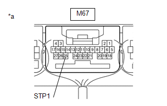
(a) Disconnect the M67 certification ECU (smart Key ECU assembly) connector.
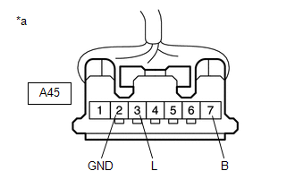
(b) Disconnect the A45 stop light switch assembly connector.
|
(c) Measure the voltage according to the value(s) in the table below. Standard Voltage:
|
|
(d) Measure the resistance according to the value(s) in the table below.
Standard Resistance:
|
Tester Connection |
Condition |
Specified Condition |
|---|---|---|
|
M67-25 (STP1) - A45-3 (L) |
Always |
Below 1 Ω |
|
A45-2 (GND) - Body ground |
Always |
Below 1 Ω |
| NG | |
REPAIR OR REPLACE HARNESS OR CONNECTOR |
|
|
5. |
CHECK CERTIFICATION ECU (SMART KEY ECU ASSEMBLY) |
(a) Reconnect the M67 certification ECU (smart Key ECU assembly) connectors.
(b) Reconnect the A45 stop light switch assembly connector.
|
(c) Measure the voltage according to the value(s) in the table below. Standard Voltage:
|
|
| OK | |
REPLACE CERTIFICATION ECU (SMART KEY ECU ASSEMBLY) |
| NG | |
REPLACE STOP LIGHT SWITCH ASSEMBLY |
 Steering Lock Position Signal Circuit Malfunction (B2285)
DESCRIPTION
This DTC is stored when the steering lock position signal sent by the steering
lock ECU (steering lock actuator or upper bracket assembly) via direct line and
the steering lock positi ...
 Runnable Signal Malfunction (B2286,P0335)
DESCRIPTION
These DTCs are stored when the engine speed signal sent by the ECM via direct
line and the engine speed signal sent via CAN communication do not match.
DTC No.
De ...
Other materials:
Toyota CH-R Service Manual > Meter / Gauge System: Operating Light Control Rheostat does not Change Light Brightness
DESCRIPTION
The illumination intensity of the combination meter is increased by turning the
knob of the light control rheostat upward, and decreased by turning the knob downward.
WIRING DIAGRAM
CAUTION / NOTICE / HINT
NOTICE:
When replacing the combination meter assembly, always replace it ...
Toyota CH-R Service Manual > Heating / Air Conditioning: Front Blower Motor(for Denso Made)
Components
COMPONENTS
ILLUSTRATION
*1
BLOWER MOTOR WITH FAN SUB-ASSEMBLY
*2
NO. 2 INSTRUMENT PANEL UNDER COVER SUB-ASSEMBLY
Removal
REMOVAL
PROCEDURE
1. REMOVE NO. 2 INSTRUMENT PANEL UNDER COVER SUB-ASSEMBLY
Click here
2. REMOVE ...
Toyota C-HR (AX20) 2023-2026 Owner's Manual
Toyota CH-R Owners Manual
- For safety and security
- Instrument cluster
- Operation of each component
- Driving
- Interior features
- Maintenance and care
- When trouble arises
- Vehicle specifications
- For owners
Toyota CH-R Service Manual
- Introduction
- Maintenance
- Audio / Video
- Cellular Communication
- Navigation / Multi Info Display
- Park Assist / Monitoring
- Brake (front)
- Brake (rear)
- Brake Control / Dynamic Control Systems
- Brake System (other)
- Parking Brake
- Axle And Differential
- Drive Shaft / Propeller Shaft
- K114 Cvt
- 3zr-fae Battery / Charging
- Networking
- Power Distribution
- Power Assist Systems
- Steering Column
- Steering Gear / Linkage
- Alignment / Handling Diagnosis
- Front Suspension
- Rear Suspension
- Tire / Wheel
- Tire Pressure Monitoring
- Door / Hatch
- Exterior Panels / Trim
- Horn
- Lighting (ext)
- Mirror (ext)
- Window / Glass
- Wiper / Washer
- Door Lock
- Heating / Air Conditioning
- Interior Panels / Trim
- Lighting (int)
- Meter / Gauge / Display
- Mirror (int)
- Power Outlets (int)
- Pre-collision
- Seat
- Seat Belt
- Supplemental Restraint Systems
- Theft Deterrent / Keyless Entry

0.0086