Toyota CH-R Service Manual: Disassembly
DISASSEMBLY
PROCEDURE
1. REMOVE STEERING RACK BOOT CLIP (for LH Side)
(a) Using pliers, remove the steering rack boot clip.
2. REMOVE STEERING RACK BOOT CLIP (for RH Side)
HINT:
Perform the same procedure as for the LH side.
3. REMOVE STEERING RACK BOOT CLAMP (for LH Side)
|
(a) Using a screwdriver, remove the steering rack boot clamp. NOTICE: Be careful not to damage the No. 2 steering rack boot. |
|
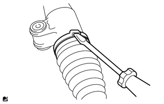
4. REMOVE STEERING RACK BOOT CLAMP (for RH Side)
HINT:
Perform the same procedure as for the LH side.
5. REMOVE NO. 2 STEERING RACK BOOT
6. REMOVE NO. 1 STEERING RACK BOOT
 Removal
REMOVAL
CAUTION / NOTICE / HINT
The necessary procedures (adjustment, calibration, initialization, or registration)
that must be performed after parts are removed and installed, or replaced during ...
 Inspection
INSPECTION
PROCEDURE
1. INSPECT TIE ROD END SUB-ASSEMBLY LH
(a) Secure the tie rod end sub-assembly LH in a vise between aluminum
plates.
NOTICE:
Do not overtighten the vise.
...
Other materials:
Toyota CH-R Service Manual > Immobiliser System(w/o Smart Key System): Engine Immobiliser System Malfunction (B2799)
DESCRIPTION
The ECM stores this DTC when the communication line between the ECM and transponder
key ECU assembly is malfunctioning or the communication ID of the ECM and transponder
key ECU assembly do not match.
DTC No.
Detection Item
DTC Detection Condition
...
Toyota CH-R Service Manual > Pre-collision System: Front Radar Sensor Incorrect Axial Gap (C1A11,C1A14)
DESCRIPTION
When the system determines that the vehicle is driving straight ahead based on
signals from the yaw rate and acceleration sensor (airbag sensor assembly), etc.,
the millimeter wave radar sensor assembly performs self-diagnosis to check if the
sensor beam axis is misaligned.
C1A11 ...
Toyota C-HR (AX20) 2023-2026 Owner's Manual
Toyota CH-R Owners Manual
- For safety and security
- Instrument cluster
- Operation of each component
- Driving
- Interior features
- Maintenance and care
- When trouble arises
- Vehicle specifications
- For owners
Toyota CH-R Service Manual
- Introduction
- Maintenance
- Audio / Video
- Cellular Communication
- Navigation / Multi Info Display
- Park Assist / Monitoring
- Brake (front)
- Brake (rear)
- Brake Control / Dynamic Control Systems
- Brake System (other)
- Parking Brake
- Axle And Differential
- Drive Shaft / Propeller Shaft
- K114 Cvt
- 3zr-fae Battery / Charging
- Networking
- Power Distribution
- Power Assist Systems
- Steering Column
- Steering Gear / Linkage
- Alignment / Handling Diagnosis
- Front Suspension
- Rear Suspension
- Tire / Wheel
- Tire Pressure Monitoring
- Door / Hatch
- Exterior Panels / Trim
- Horn
- Lighting (ext)
- Mirror (ext)
- Window / Glass
- Wiper / Washer
- Door Lock
- Heating / Air Conditioning
- Interior Panels / Trim
- Lighting (int)
- Meter / Gauge / Display
- Mirror (int)
- Power Outlets (int)
- Pre-collision
- Seat
- Seat Belt
- Supplemental Restraint Systems
- Theft Deterrent / Keyless Entry

0.0108