Toyota CH-R Service Manual: Inspection
INSPECTION
PROCEDURE
1. INSPECT TIE ROD END SUB-ASSEMBLY LH
|
(a) Secure the tie rod end sub-assembly LH in a vise between aluminum plates. NOTICE: Do not overtighten the vise. |
|
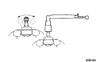
(b) Install the nut to the stud bolt.
(c) Flip the ball joint back and forth 5 times.
(d) Using a torque wrench and the nut, turn the stud bolt continuously at a rate of 2 to 4 seconds per turn, and check the turning torque on the 5th turn.
Standard Turning Torque:
0.49 to 3.43 N*m (5 to 34 kgf*cm, 5 to 30 in.*lbf)
If the turning torque is not within the specified range, replace the tie rod end sub-assembly LH with a new one.
(e) Check that the dust cover is not cracked and that there is no grease on it.
If the dust cover is cracked or there is grease on it, replace the tie rod end sub-assembly LH with a new one.
2. INSPECT TIE ROD END SUB-ASSEMBLY RH
HINT:
Perform the same procedure as for the LH side.
3. INSPECT TOTAL PRELOAD
NOTICE:
Inspect the total preload in a no-load condition by removing the tie rod end sub-assemblies RH and LH, and steering rack boots.
|
(a) Install SST to the pinion shaft and turn it left and right 5 times or more. SST: 09616-00020 |
|
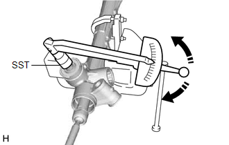
(b) Using SST and a torque wrench, turn the pinion shaft continuously at a rate of 4 to 6 seconds per turn to inspect the total preload of the steering gear assembly.
Standard Preload:
1.5 to 2.4 N*m (16 to 24 kgf*cm, 14 to 21 in.*lbf)
NOTICE:
Inspect the total preload around the steering rack center position.
If the total preload is not within the specified range, replace the steering gear assembly with a new one.
 Disassembly
DISASSEMBLY
PROCEDURE
1. REMOVE STEERING RACK BOOT CLIP (for LH Side)
(a) Using pliers, remove the steering rack boot clip.
2. REMOVE STEERING RACK BOOT CLIP (for RH Side)
HINT:
Perform the same ...
 Installation
INSTALLATION
PROCEDURE
1. INSTALL TIE ROD END SUB-ASSEMBLY LH
(a) Install the lock nut and tie rod end sub-assembly LH to the steering
gear assembly until the matchmarks are aligned. ...
Other materials:
Toyota CH-R Owners Manual > Instrument cluster: Gauges and meters
The units used on the speedometer may differ depending on the target region.
Tachometer
Displays the engine speed in revolutions per minute.
Multi-information display
Presents the driver with a variety of driving-related data.
Displays warning messages in case of a malfunction.
S ...
Toyota CH-R Owners Manual > Using the driving support systems: PCS (Pre-Collision System)
The pre-collision system uses a radar sensor and camera sensor to
detect vehicles and pedestrians in front of your vehicle.
When the system determines that the possibility of a frontal collision with a
vehicle or pedestrian is high, a warning operates to urge the driver to take evasive
acti ...
Toyota C-HR (AX20) 2023-2026 Owner's Manual
Toyota CH-R Owners Manual
- For safety and security
- Instrument cluster
- Operation of each component
- Driving
- Interior features
- Maintenance and care
- When trouble arises
- Vehicle specifications
- For owners
Toyota CH-R Service Manual
- Introduction
- Maintenance
- Audio / Video
- Cellular Communication
- Navigation / Multi Info Display
- Park Assist / Monitoring
- Brake (front)
- Brake (rear)
- Brake Control / Dynamic Control Systems
- Brake System (other)
- Parking Brake
- Axle And Differential
- Drive Shaft / Propeller Shaft
- K114 Cvt
- 3zr-fae Battery / Charging
- Networking
- Power Distribution
- Power Assist Systems
- Steering Column
- Steering Gear / Linkage
- Alignment / Handling Diagnosis
- Front Suspension
- Rear Suspension
- Tire / Wheel
- Tire Pressure Monitoring
- Door / Hatch
- Exterior Panels / Trim
- Horn
- Lighting (ext)
- Mirror (ext)
- Window / Glass
- Wiper / Washer
- Door Lock
- Heating / Air Conditioning
- Interior Panels / Trim
- Lighting (int)
- Meter / Gauge / Display
- Mirror (int)
- Power Outlets (int)
- Pre-collision
- Seat
- Seat Belt
- Supplemental Restraint Systems
- Theft Deterrent / Keyless Entry

0.0071