Toyota CH-R Service Manual: Installation
INSTALLATION
PROCEDURE
1. INSTALL INSTRUMENT CLUSTER FINISH PANEL CENTER GARNISH
(a) Engage the claws to install the instrument cluster finish panel center garnish as shown in the illustration.
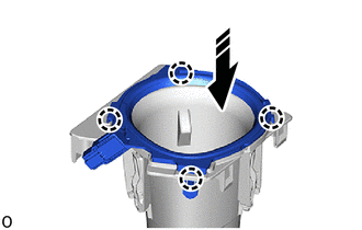
.png) |
Install in this Direction |
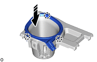
2. INSTALL INSTRUMENT CLUSTER FINISH PANEL GARNISH
(a) Engage the claws to install the instrument cluster finish panel garnish as shown in the illustration.
|
|
Install in this Direction |
3. INSTALL NO. 2 CONSOLE BOX CUP HOLDER
Click here .gif)
4. INSTALL CONSOLE BOX CUP HOLDER
Click here
5. INSTALL CONSOLE UPPER PANEL SUB-ASSEMBLY
Click here
6. INSTALL SHIFT LEVER KNOB SUB-ASSEMBLY
Click here
7. INSTALL INSTRUMENT PANEL BOX ASSEMBLY
Click here
8. INSTALL INSTRUMENT PANEL LOWER CENTER FINISH PANEL
Click here
9. INSTALL INSTRUMENT CLUSTER FINISH PANEL GARNISH ASSEMBLY
Click here
10. INSTALL NO. 1 INSTRUMENT PANEL UNDER COVER SUB-ASSEMBLY
Click here
11. INSTALL COWL SIDE TRIM BOARD LH
Click here
12. INSTALL FRONT DOOR SCUFF PLATE LH
Click here
 Inspection
INSPECTION
PROCEDURE
1. INSPECT INSTRUMENT CLUSTER FINISH PANEL GARNISH
(a) Check that the LED illuminates.
(1) Apply battery voltage to the instrument cluster finish panel garnish
...

Other materials:
Toyota CH-R Owners Manual > If you have a flat tire: Replacing a flat tire
1. Chock the tires.
Flat tire
Wheel chock positions
Front
Left-hand side
Behind the rear right-hand side tire
Right-hand side
Behind the rear left-hand side tire
Rear
Left-hand side
In front of the front right-hand side tire
Right-han ...
Toyota CH-R Service Manual > Occupant Classification System: Yaw Rate Sensor Module Malfunction (B1798,B1799)
DESCRIPTION
The occupant detection ECU receives signals from the acceleration sensor (airbag
sensor assembly) and skid control ECU via CAN communication.
DTC No.
Detection Item
DTC Detection Condition
Trouble Area
B1798
Yaw ...
Toyota C-HR (AX20) 2023-2026 Owner's Manual
Toyota CH-R Owners Manual
- For safety and security
- Instrument cluster
- Operation of each component
- Driving
- Interior features
- Maintenance and care
- When trouble arises
- Vehicle specifications
- For owners
Toyota CH-R Service Manual
- Introduction
- Maintenance
- Audio / Video
- Cellular Communication
- Navigation / Multi Info Display
- Park Assist / Monitoring
- Brake (front)
- Brake (rear)
- Brake Control / Dynamic Control Systems
- Brake System (other)
- Parking Brake
- Axle And Differential
- Drive Shaft / Propeller Shaft
- K114 Cvt
- 3zr-fae Battery / Charging
- Networking
- Power Distribution
- Power Assist Systems
- Steering Column
- Steering Gear / Linkage
- Alignment / Handling Diagnosis
- Front Suspension
- Rear Suspension
- Tire / Wheel
- Tire Pressure Monitoring
- Door / Hatch
- Exterior Panels / Trim
- Horn
- Lighting (ext)
- Mirror (ext)
- Window / Glass
- Wiper / Washer
- Door Lock
- Heating / Air Conditioning
- Interior Panels / Trim
- Lighting (int)
- Meter / Gauge / Display
- Mirror (int)
- Power Outlets (int)
- Pre-collision
- Seat
- Seat Belt
- Supplemental Restraint Systems
- Theft Deterrent / Keyless Entry

0.0073