Toyota CH-R Service Manual: Inspection
INSPECTION
PROCEDURE
1. INSPECT INSTRUMENT CLUSTER FINISH PANEL GARNISH
|
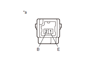
(a) Check that the LED illuminates. (1) Apply battery voltage to the instrument cluster finish panel garnish and check that the LED illuminates. OK:
If the result is not as specified, replace the instrument cluster finish panel garnish. |
|
2. INSPECT INSTRUMENT CLUSTER FINISH PANEL CENTER GARNISH
|
(a) Check that the LED illuminates. (1) Apply battery voltage to the instrument cluster finish panel center garnish and check that the LED illuminates. OK:
If the result is not as specified, replace the instrument cluster finish panel center garnish. |
|
 Removal
REMOVAL
PROCEDURE
1. REMOVE FRONT DOOR SCUFF PLATE LH
Click here
2. REMOVE COWL SIDE TRIM BOARD LH
Click here
3. REMOVE NO. 1 INSTRUMENT PANEL UNDER COVER SUB-ASSEMBLY
Click here
4. REMO ...
 Installation
INSTALLATION
PROCEDURE
1. INSTALL INSTRUMENT CLUSTER FINISH PANEL CENTER GARNISH
(a) Engage the claws to install the instrument cluster finish panel center garnish
as shown in the illustration.
...
Other materials:
Toyota CH-R Service Manual > Lighting System: Footwell Light Circuit
DESCRIPTION
The main body ECU (multiplex network body ECU) controls the door mirror foot
lights.
WIRING DIAGRAM
PROCEDURE
1.
PERFORM ACTIVE TEST USING TECHSTREAM
(a) Connect the Techstream to the DLC3.
(b) Turn the ignition switch to ON.
(c) Turn the Techst ...
Toyota CH-R Service Manual > Rear Shock Absorber: Disposal
DISPOSAL
PROCEDURE
1. DISPOSE OF REAR SHOCK ABSORBER ASSEMBLY
(a) Extend the piston rod and secure the rear shock absorber assembly
at an angle in a vise.
(b) Using a hacksaw, slowly make a hole at the position indicated by the arrow ...
Toyota C-HR (AX20) 2023-2026 Owner's Manual
Toyota CH-R Owners Manual
- For safety and security
- Instrument cluster
- Operation of each component
- Driving
- Interior features
- Maintenance and care
- When trouble arises
- Vehicle specifications
- For owners
Toyota CH-R Service Manual
- Introduction
- Maintenance
- Audio / Video
- Cellular Communication
- Navigation / Multi Info Display
- Park Assist / Monitoring
- Brake (front)
- Brake (rear)
- Brake Control / Dynamic Control Systems
- Brake System (other)
- Parking Brake
- Axle And Differential
- Drive Shaft / Propeller Shaft
- K114 Cvt
- 3zr-fae Battery / Charging
- Networking
- Power Distribution
- Power Assist Systems
- Steering Column
- Steering Gear / Linkage
- Alignment / Handling Diagnosis
- Front Suspension
- Rear Suspension
- Tire / Wheel
- Tire Pressure Monitoring
- Door / Hatch
- Exterior Panels / Trim
- Horn
- Lighting (ext)
- Mirror (ext)
- Window / Glass
- Wiper / Washer
- Door Lock
- Heating / Air Conditioning
- Interior Panels / Trim
- Lighting (int)
- Meter / Gauge / Display
- Mirror (int)
- Power Outlets (int)
- Pre-collision
- Seat
- Seat Belt
- Supplemental Restraint Systems
- Theft Deterrent / Keyless Entry

0.0095