Toyota CH-R Service Manual: Removal
REMOVAL
PROCEDURE
1. REMOVE FRONT DOOR SCUFF PLATE LH
Click here .gif)
2. REMOVE COWL SIDE TRIM BOARD LH
Click here
3. REMOVE NO. 1 INSTRUMENT PANEL UNDER COVER SUB-ASSEMBLY
Click here
4. REMOVE INSTRUMENT CLUSTER FINISH PANEL GARNISH ASSEMBLY
Click here
5. REMOVE INSTRUMENT PANEL LOWER CENTER FINISH PANEL
Click here
6. REMOVE INSTRUMENT PANEL BOX ASSEMBLY
Click here
7. REMOVE SHIFT LEVER KNOB SUB-ASSEMBLY
Click here
8. REMOVE CONSOLE UPPER PANEL SUB-ASSEMBLY
Click here
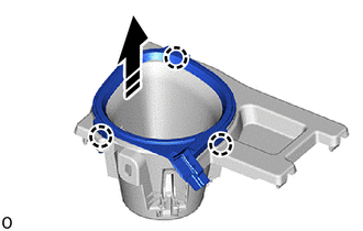
9. REMOVE CONSOLE BOX CUP HOLDER
Click here
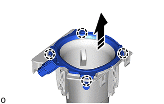
10. REMOVE NO. 2 CONSOLE BOX CUP HOLDER
Click here
11. REMOVE INSTRUMENT CLUSTER FINISH PANEL GARNISH
(a) Disengage the claws to remove the instrument cluster finish panel garnish as shown in the illustration.
.png) |
Remove in this Direction |
12. REMOVE INSTRUMENT CLUSTER FINISH PANEL CENTER GARNISH
(a) Disengage the claws to remove the instrument cluster finish panel center garnish as shown in the illustration.
|
|
Remove in this Direction |
 Components
COMPONENTS
ILLUSTRATION
*1
COWL SIDE TRIM BOARD LH
*2
FRONT DOOR SCUFF PLATE LH
*3
INSTRUMENT CLUSTER FINISH PANEL GARNISH A ...
 Inspection
INSPECTION
PROCEDURE
1. INSPECT INSTRUMENT CLUSTER FINISH PANEL GARNISH
(a) Check that the LED illuminates.
(1) Apply battery voltage to the instrument cluster finish panel garnish
...
Other materials:
Toyota CH-R Service Manual > Power Window Control System: Fail-safe Chart
FAIL-SAFE CHART
PULSE FAILURE
(a) If a pulse sensor built into the power window regulator motor assembly malfunctions,
the following power window operations will be prohibited.
Multiplex Network Master Switch Assembly, Power Window Regulator Switch Assembly,
Rear Power Window Regulator Switch ...
Toyota CH-R Service Manual > Rear Combination Light Assembly(for Led Type): Removal
REMOVAL
CAUTION / NOTICE / HINT
HINT:
Use the same procedure for the RH side and LH side.
The following procedure is for the LH side.
PROCEDURE
1. REMOVE REAR COMBINATION LIGHT COVER
(a) Disengage the claws to remove the rear combination light cover as shown in
the illustra ...
Toyota C-HR (AX20) 2023-2026 Owner's Manual
Toyota CH-R Owners Manual
- For safety and security
- Instrument cluster
- Operation of each component
- Driving
- Interior features
- Maintenance and care
- When trouble arises
- Vehicle specifications
- For owners
Toyota CH-R Service Manual
- Introduction
- Maintenance
- Audio / Video
- Cellular Communication
- Navigation / Multi Info Display
- Park Assist / Monitoring
- Brake (front)
- Brake (rear)
- Brake Control / Dynamic Control Systems
- Brake System (other)
- Parking Brake
- Axle And Differential
- Drive Shaft / Propeller Shaft
- K114 Cvt
- 3zr-fae Battery / Charging
- Networking
- Power Distribution
- Power Assist Systems
- Steering Column
- Steering Gear / Linkage
- Alignment / Handling Diagnosis
- Front Suspension
- Rear Suspension
- Tire / Wheel
- Tire Pressure Monitoring
- Door / Hatch
- Exterior Panels / Trim
- Horn
- Lighting (ext)
- Mirror (ext)
- Window / Glass
- Wiper / Washer
- Door Lock
- Heating / Air Conditioning
- Interior Panels / Trim
- Lighting (int)
- Meter / Gauge / Display
- Mirror (int)
- Power Outlets (int)
- Pre-collision
- Seat
- Seat Belt
- Supplemental Restraint Systems
- Theft Deterrent / Keyless Entry

0.0102