Toyota CH-R Service Manual: Footwell Light Circuit
DESCRIPTION
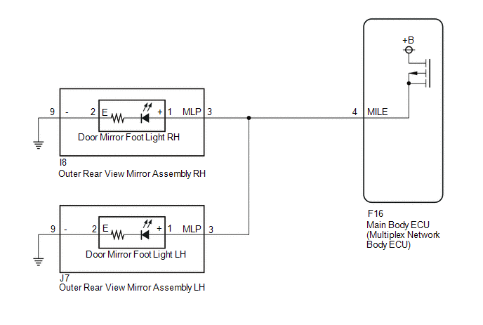
The main body ECU (multiplex network body ECU) controls the door mirror foot lights.
WIRING DIAGRAM
PROCEDURE
|
1. |
PERFORM ACTIVE TEST USING TECHSTREAM |
(a) Connect the Techstream to the DLC3.
(b) Turn the ignition switch to ON.
(c) Turn the Techstream on.
(d) Enter the following menus: Body Electrical / Main Body / Active Test.
(e) Perform the Active Test according to the display on the Techstream.
Body Electrical > Main Body > Active Test|
Tester Display |
Measurement Item |
Control Range |
Diagnostic Note |
|---|---|---|---|
|
Side Mirror Foot Light |
Door mirror foot lights |
ON or OFF |
- |
|
Tester Display |
|---|
|
Side Mirror Foot Light |
OK:
Door mirror foot lights illuminate.
|
Result |
Proceed to |
|---|---|
|
OK |
A |
|
NG (for LH Side) |
B |
|
NG (for RH Side) |
C |
| A | .gif) |
PROCEED TO NEXT SUSPECTED AREA SHOWN IN PROBLEM SYMPTOMS TABLE
|
| C | |
GO TO STEP 5 |
|
.gif)
|
2. |
CHECK OUTER REAR VIEW MIRROR ASSEMBLY LH (POWER SOURCE) |
(a) Disconnect the J7 outer rear view mirror assembly LH connector.
(b) Measure the voltage according to the value(s) in the table below.
Standard Voltage:
|
Tester Connection |
Condition |
Specified Condition |
|---|---|---|
|
J7-3 (MLP) - Body ground |
Illumination conditions of door mirror foot light met* |
11 to 14 V |
- *: Refer to System Description for the illumination conditions of the
outer rear view mirror assembly light.
Click here
.gif)
| NG | |
REPAIR OR REPLACE HARNESS OR CONNECTOR |
|
|
3. |
INSPECT DOOR MIRROR FOOT LIGHT LH |
(a) Remove the door mirror foot light LH.
Click here
|
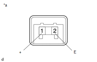
(b) Check the door mirror foot light LH illumination. (1) Apply battery voltage between the terminals of the door mirror footwell light LH and check the illumination condition of the door mirror footwell light LH. OK:
|
|
| NG | |
REPLACE DOOR MIRROR FOOT LIGHT LH |
|
|
4. |
CHECK HARNESS AND CONNECTOR (OUTER REAR VIEW MIRROR ASSEMBLY LH - BODY GROUND) |
(a) Disconnect the J7 outer rear view mirror assembly LH.
(b) Measure the resistance according to the value(s) in the table below.
Standard Resistance:
|
Tester Connection |
Condition |
Specified Condition |
|---|---|---|
|
J7-9 (-) - Body ground |
Always |
Below 1 Ω |
| OK | |
REPLACE OUTER REAR VIEW MIRROR ASSEMBLY LH
|
| NG | |
REPAIR OR REPLACE HARNESS OR CONNECTOR |
|
5. |
CHECK OUTER REAR VIEW MIRROR ASSEMBLY RH (POWER SOURCE) |
(a) Disconnect the I8 outer rear view mirror assembly RH connector.
(b) Measure the voltage according to the value(s) in the table below.
Standard Voltage:
|
Tester Connection |
Condition |
Specified Condition |
|---|---|---|
|
I8-3 (MLP) - Body ground |
Illumination conditions of door mirror foot light met* |
11 to 14 V |
- *: Refer to System Description for the illumination conditions of the
outer rear view mirror assembly light.
Click here
| NG | |
REPAIR OR REPLACE HARNESS OR CONNECTOR |
|
|
6. |
INSPECT DOOR MIRROR FOOT LIGHT RH |
(a) Remove the door mirror foot light RH.
Click here
|
(b) Check the door mirror foot light RH illumination. (1) Apply battery voltage between the terminals of the door mirror footwell light RH and check the illumination condition of the door mirror footwell light RH. OK:
|
|
| NG | |
REPLACE DOOR MIRROR FOOT LIGHT RH |
|
|
7. |
CHECK HARNESS AND CONNECTOR (OUTER REAR VIEW MIRROR ASSEMBLY RH - BODY GROUND) |
(a) Disconnect the I8 outer rear view mirror assembly RH.
(b) Measure the resistance according to the value(s) in the table below.
Standard Resistance:
|
Tester Connection |
Condition |
Specified Condition |
|---|---|---|
|
I8-9 (-) - Body ground |
Always |
Below 1 Ω |
| OK | |
REPLACE OUTER REAR VIEW MIRROR ASSEMBLY RH
|
| NG | |
REPAIR OR REPLACE HARNESS OR CONNECTOR |
 Front Fog Light Circuit
DESCRIPTION
The main body ECU (multiplex network body ECU) controls the front fog lights.
WIRING DIAGRAM
CAUTION / NOTICE / HINT
NOTICE:
Inspect the fuses and bulbs for circuits related ...
 Hazard Warning Switch Circuit
DESCRIPTION
The combination meter assembly receives the hazard warning signal switch assembly
on signal and controls the operation of the hazard warning lights.
WIRING DIAGRAM
CAUTION / NOTICE ...
Other materials:
Toyota CH-R Service Manual > Audio And Visual System(for Radio And Display Type): Panel Switches do not Function
CAUTION / NOTICE / HINT
NOTICE:
Depending on the parts that are replaced during vehicle inspection or
maintenance, performing initialization, registration or calibration may
be needed. Refer to Precaution for Audio and Visual System.
Click here
When replacing the ...
Toyota CH-R Service Manual > Lighting (int): Vanity Light Switch
Components
COMPONENTS
ILLUSTRATION
*1
VISOR ASSEMBLY
*2
VISOR BRACKET COVER
Inspection
INSPECTION
PROCEDURE
1. INSPECT VISOR ASSEMBLY LH
(a) Check the resistance.
(1) Measure the resistance according to the value(s) in ...
Toyota C-HR (AX20) 2023-2026 Owner's Manual
Toyota CH-R Owners Manual
- For safety and security
- Instrument cluster
- Operation of each component
- Driving
- Interior features
- Maintenance and care
- When trouble arises
- Vehicle specifications
- For owners
Toyota CH-R Service Manual
- Introduction
- Maintenance
- Audio / Video
- Cellular Communication
- Navigation / Multi Info Display
- Park Assist / Monitoring
- Brake (front)
- Brake (rear)
- Brake Control / Dynamic Control Systems
- Brake System (other)
- Parking Brake
- Axle And Differential
- Drive Shaft / Propeller Shaft
- K114 Cvt
- 3zr-fae Battery / Charging
- Networking
- Power Distribution
- Power Assist Systems
- Steering Column
- Steering Gear / Linkage
- Alignment / Handling Diagnosis
- Front Suspension
- Rear Suspension
- Tire / Wheel
- Tire Pressure Monitoring
- Door / Hatch
- Exterior Panels / Trim
- Horn
- Lighting (ext)
- Mirror (ext)
- Window / Glass
- Wiper / Washer
- Door Lock
- Heating / Air Conditioning
- Interior Panels / Trim
- Lighting (int)
- Meter / Gauge / Display
- Mirror (int)
- Power Outlets (int)
- Pre-collision
- Seat
- Seat Belt
- Supplemental Restraint Systems
- Theft Deterrent / Keyless Entry

0.0101