Toyota CH-R Service Manual: Front Fog Light Circuit
DESCRIPTION
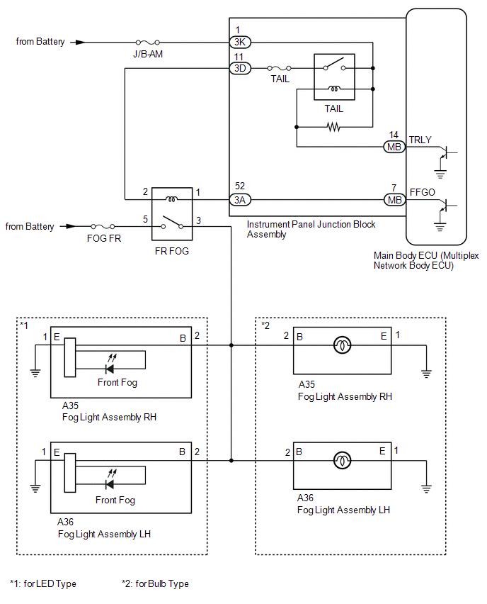
The main body ECU (multiplex network body ECU) controls the front fog lights.
WIRING DIAGRAM
CAUTION / NOTICE / HINT
NOTICE:
- Inspect the fuses and bulbs for circuits related to this system before performing the following procedure.
- Before replacing the main body ECU (multiplex network body ECU), refer
to Registration.*1
Click here
.gif)
- *1: w/ Smart Key System
PROCEDURE
|
1. |
CHECK OPERATION (TAILLIGHTS) |
(a) Check the operation of the taillights.
OK:
Taillights operate normally.
| NG | .gif) |
GO TO PROBLEM SYMPTOMS TABLE |
|
.gif)
|
2. |
PERFORM ACTIVE TEST USING TECHSTREAM |
(a) Connect the Techstream to the DLC3.
(b) Turn the ignition switch to ON.
(c) Turn the Techstream on.
(d) Enter the following menus: Body Electrical / Main Body / Active Test.
(e) Perform the Active Test according to the display on the Techstream.
Body Electrical > Main Body > Active Test|
Tester Display |
Measurement Item |
Control Range |
Diagnostic Note |
|---|---|---|---|
|
Front Fog Light Relay |
Front fog lights |
ON/OFF |
Light control switch in tail position |
|
Tester Display |
|---|
|
Front Fog Light Relay |
OK:
Front fog lights come on.
| OK | |
PROCEED TO NEXT SUSPECTED AREA SHOWN IN PROBLEM SYMPTOMS TABLE |
|
|
3. |
CHECK HARNESS AND CONNECTOR (FR FOG RELAY - BATTERY) |
(a) Remove the FR FOG relay from the No. 4 relay block assembly.
(b) Measure the voltage according to the value(s) in the table below.
Standard Voltage:
|
Tester Connection |
Condition |
Specified Condition |
|---|---|---|
|
Relay terminal 5 -Body ground |
Always |
11 to 14 V |
| NG | |
REPAIR OR REPLACE HARNESS OR CONNECTOR |
|
|
4. |
CHECK HARNESS AND CONNECTOR (FR FOG RELAY INPUT VOLTAGE) |
(a) Measure the voltage according to the value(s) in the table below.
Standard Voltage:
|
Tester Connection |
Condition |
Specified Condition |
|---|---|---|
|
Relay terminal 2 - Body ground |
Light control switch TAIL or HEAD |
11 to 14 V |
| NG | |
GO TO STEP 9 |
|
|
5. |
INSPECT FR FOG RELAY |
(a) Inspect the FR FOG relay.
Click here
| NG | |
REPLACE FR FOG RELAY |
|
|
6. |
CHECK HARNESS AND CONNECTOR (FR FOG RELAY - FOG LIGHT ASSEMBLY RH AND FOG LIGHT ASSEMBLY LH) |
(a) Disconnect the A36 fog light assembly LH connector.
(b) Disconnect the A35 fog light assembly RH connector.
(c) Measure the voltage according to the value(s) in the table below.
Standard Resistance:
|
Tester Connection |
Condition |
Specified Condition |
|---|---|---|
|
Relay terminal 3 - A36-2 (B) |
Always |
Below 1 Ω |
|
Relay terminal 3 - A35-2 (B) |
Always |
Below 1 Ω |
|
Relay terminal 3 or A36-2 (B) - Body ground |
Always |
10 kΩ or higher |
|
Relay terminal 3 or A35-2 (B) - Body ground |
Always |
10 kΩ or higher |
| NG | |
REPAIR OR REPLACE HARNESS OR CONNECTOR |
|
|
7. |
CHECK HARNESS AND CONNECTOR (FR FOG RELAY - INSTRUMENT PANEL JUNCTION BLOCK ASSEMBLY) |
(a) Disconnect the 3A instrument panel junction block assembly connector.
(b) Measure the voltage according to the value(s) in the table below.
Standard Resistance:
|
Tester Connection |
Condition |
Specified Condition |
|---|---|---|
|
Relay terminal 1 - 3A-52 |
Always |
Below 1 Ω |
|
Relay terminal 1 or 3A-52 - Body ground |
Always |
10 kΩ or higher |
| NG | |
REPAIR OR REPLACE HARNESS OR CONNECTOR |
|
|
8. |
INSPECT INSTRUMENT PANEL JUNCTION BLOCK ASSEMBLY |
(a) Remove the instrument panel junction block assembly.
Click here
(b) Remove the main body ECU (multiplex network body ECU) from the instrument panel junction block assembly.
(c) Measure the resistance according to the value(s) in the table below.
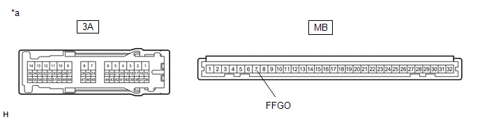
|
*a |
Component without harness connected (Instrument Panel Junction Block Assembly) |
- |
- |
Standard Resistance:
|
Tester Connection |
Condition |
Specified Condition |
|---|---|---|
|
3A-52 - MB-7 (FFGO) |
Always |
Below 1 Ω |
| OK | |
REPLACE MAIN BODY ECU (MULTIPLEX NETWORK BODY ECU) |
| NG | |
REPLACE INSTRUMENT PANEL JUNCTION BLOCK ASSEMBLY |
|
9. |
CHECK HARNESS AND CONNECTOR (FR FOG RELAY - INSTRUMENT PANEL JUNCTION BLOCK ASSEMBLY) |
(a) Disconnect the 3D instrument panel junction block assembly connector.
(b) Measure the voltage according to the value(s) in the table below.
Standard Resistance:
|
Tester Connection |
Condition |
Specified Condition |
|---|---|---|
|
Relay terminal 2 - 3D-11 |
Always |
Below 1 Ω |
|
Relay terminal 2 or 3D-11 - Body ground |
Always |
10 kΩ or higher |
| OK | |
REPLACE INSTRUMENT PANEL JUNCTION BLOCK ASSEMBLY |
| NG | |
REPAIR OR REPLACE HARNESS OR CONNECTOR |
 Clearance Light/Daytime Running Light Circuit
DESCRIPTION
Clearance light function:
When the main body ECU (multiplex network body ECU) receives the light
control switch position signal, it sends an illumination request signal
t ...
 Footwell Light Circuit
DESCRIPTION
The main body ECU (multiplex network body ECU) controls the door mirror foot
lights.
WIRING DIAGRAM
PROCEDURE
1.
PERFORM ACTIVE TEST USING TECHSTREAM
...
Other materials:
Toyota CH-R Service Manual > Rear Brake(for Tmmt Made): Components
COMPONENTS
ILLUSTRATION
*1
NO. 2 PARKING BRAKE WIRE ASSEMBLY
*2
PARKING BRAKE ACTUATOR ASSEMBLY
*3
O-RING
-
-
Tightening torque for "Major areas involving basic vehicle pe ...
Toyota CH-R Service Manual > Air Conditioning Unit(for Valeo Made): Reassembly
REASSEMBLY
PROCEDURE
1. INSTALL NO. 1 COOLER THERMISTOR
Click here
2. INSTALL NO. 2 RADIATOR CASE SUB-ASSEMBLY
(a) Install the No. 2 radiator case sub-assembly with the 6 screws.
3. INSTALL NO. 1 COOLER EVAPORATOR SUB-ASSEMBLY
...
Toyota C-HR (AX20) 2023-2026 Owner's Manual
Toyota CH-R Owners Manual
- For safety and security
- Instrument cluster
- Operation of each component
- Driving
- Interior features
- Maintenance and care
- When trouble arises
- Vehicle specifications
- For owners
Toyota CH-R Service Manual
- Introduction
- Maintenance
- Audio / Video
- Cellular Communication
- Navigation / Multi Info Display
- Park Assist / Monitoring
- Brake (front)
- Brake (rear)
- Brake Control / Dynamic Control Systems
- Brake System (other)
- Parking Brake
- Axle And Differential
- Drive Shaft / Propeller Shaft
- K114 Cvt
- 3zr-fae Battery / Charging
- Networking
- Power Distribution
- Power Assist Systems
- Steering Column
- Steering Gear / Linkage
- Alignment / Handling Diagnosis
- Front Suspension
- Rear Suspension
- Tire / Wheel
- Tire Pressure Monitoring
- Door / Hatch
- Exterior Panels / Trim
- Horn
- Lighting (ext)
- Mirror (ext)
- Window / Glass
- Wiper / Washer
- Door Lock
- Heating / Air Conditioning
- Interior Panels / Trim
- Lighting (int)
- Meter / Gauge / Display
- Mirror (int)
- Power Outlets (int)
- Pre-collision
- Seat
- Seat Belt
- Supplemental Restraint Systems
- Theft Deterrent / Keyless Entry

0.0111