Toyota CH-R Service Manual: Clearance Light/Daytime Running Light Circuit
DESCRIPTION
- When the main body ECU (multiplex network body ECU) receives the light control switch position signal, it sends an illumination request signal to the headlight ECU sub-assembly LH and illuminates the clearance lights.
- When the operation conditions of the daytime running lights are met, the main body ECU (multiplex network body ECU) sends an illumination request signal to the headlight ECU sub-assembly LH and illuminates the daytime running lights.
WIRING DIAGRAM
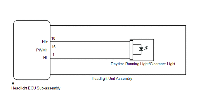
CAUTION / NOTICE / HINT
NOTICE:
If the headlight ECU sub-assembly LH has been replaced, it is necessary to synchronize the vehicle information and initialize the headlight ECU sub-assembly LH.
Click here
.gif)
PROCEDURE
|
1. |
PERFORM ACTIVE TEST USING TECHSTREAM |
(a) Connect the Techstream to the DLC3.
(b) Turn the ignition switch to ON.
(c) Enter the following menus: Body Electrical / HL AutoLeveling / Active Test.
(d) Perform the Active Test according to the display on the Techstream.
Body Electrical > HL AutoLeveling > Active Test|
Tester Display |
Measurement Item |
Control Range |
Diagnostic Note |
|---|---|---|---|
|
Clearance Light |
Clearance lights |
ON or OFF |
- |
|
Daytime Running Light |
Daytime running lights |
ON or OFF |
- |
|
Tester Display |
|---|
|
Clearance Light |
|
Tester Display |
|---|
|
Daytime Running Light |
OK:
Clearance lights and daytime running lights illuminate.
|
Result |
Proceed to |
|---|---|
|
OK |
A |
|
NG (for LH Side) |
B |
|
NG (for RH Side) |
C |
| A | .gif) |
PROCEED TO NEXT SUSPECTED AREA SHOWN IN PROBLEM SYMPTOMS TABLE |
| C | |
GO TO STEP 3 |
|
.gif)
|
2. |
REPLACE HEADLIGHT UNIT ASSEMBLY LH |
(a) Replace the headlight unit assembly LH with a new or known good one.
- for Halogen Headlight: Click here
- for LED Headlight: Click here
(b) Check that the clearance light LH and daytime running light LH operate normally.
OK:
Clearance light LH and daytime running light LH operate normally.
| OK | |
END (HEADLIGHT UNIT ASSEMBLY LH WAS DEFECTIVE) |
| NG | |
REPLACE HEADLIGHT ECU SUB-ASSEMBLY LH |
|
3. |
REPLACE HEADLIGHT UNIT ASSEMBLY RH |
(a) Replace the headlight unit assembly RH with a new or known good one.
- for Halogen Headlight: Click here
- for LED Headlight: Click here
(b) Check that the clearance light RH and daytime running light RH operate normally.
OK:
Clearance light RH and daytime running light RH operate normally.
| OK | |
END (HEADLIGHT UNIT ASSEMBLY RH WAS DEFECTIVE) |
| NG | |
REPLACE HEADLIGHT ECU SUB-ASSEMBLY RH |
 Daytime Running Light Relay Circuit
DESCRIPTION
The main body ECU (multiplex network body ECU) controls the daytime running lights.
WIRING DIAGRAM
CAUTION / NOTICE / HINT
NOTICE:
Inspect the fuses for circuits related to ...
 Front Fog Light Circuit
DESCRIPTION
The main body ECU (multiplex network body ECU) controls the front fog lights.
WIRING DIAGRAM
CAUTION / NOTICE / HINT
NOTICE:
Inspect the fuses and bulbs for circuits related ...
Other materials:
Toyota CH-R Service Manual > Cellular Communication: Telephone And Gps Antenna(for Roof Side)
Components
COMPONENTS
ILLUSTRATION
*1
TELEPHONE AND GPS ANTENNA ASSEMBLY
*2
ANTENNA OUTER COVER
*3
HOLDER
*4
SEAL
N*m (kgf*cm, ft.*lbf): Specified torque
●
...
Toyota CH-R Service Manual > Power Mirror Control System: System Diagram
SYSTEM DIAGRAM
ELECTRICAL REMOTE CONTROL MIRROR FUNCTION (w/o Retract Mirror)
ELECTRICAL REMOTE CONTROL MIRROR FUNCTION (w/ Retract Mirror)
MIRROR HEATER FUNCTION
Communication Table
Sender
Receiver
Signal
Communication Method
...
Toyota C-HR (AX20) 2023-2026 Owner's Manual
Toyota CH-R Owners Manual
- For safety and security
- Instrument cluster
- Operation of each component
- Driving
- Interior features
- Maintenance and care
- When trouble arises
- Vehicle specifications
- For owners
Toyota CH-R Service Manual
- Introduction
- Maintenance
- Audio / Video
- Cellular Communication
- Navigation / Multi Info Display
- Park Assist / Monitoring
- Brake (front)
- Brake (rear)
- Brake Control / Dynamic Control Systems
- Brake System (other)
- Parking Brake
- Axle And Differential
- Drive Shaft / Propeller Shaft
- K114 Cvt
- 3zr-fae Battery / Charging
- Networking
- Power Distribution
- Power Assist Systems
- Steering Column
- Steering Gear / Linkage
- Alignment / Handling Diagnosis
- Front Suspension
- Rear Suspension
- Tire / Wheel
- Tire Pressure Monitoring
- Door / Hatch
- Exterior Panels / Trim
- Horn
- Lighting (ext)
- Mirror (ext)
- Window / Glass
- Wiper / Washer
- Door Lock
- Heating / Air Conditioning
- Interior Panels / Trim
- Lighting (int)
- Meter / Gauge / Display
- Mirror (int)
- Power Outlets (int)
- Pre-collision
- Seat
- Seat Belt
- Supplemental Restraint Systems
- Theft Deterrent / Keyless Entry

0.0086