Toyota CH-R Service Manual: TC and CG Terminal Circuit
DESCRIPTION
DTC output mode is set by connecting terminals TC and CG of the DLC3.
DTCs are displayed by blinking of the SRS warning light.
HINT:
- When multiple warning lights in the combination meter blink continuously, a short to ground in the wiring or an ECU connected to terminal TC of the DLC3 is suspected.
- A DTC output mode signal is transmitted via CAN communication to each ECU including the airbag sensor assembly. Thus when multiple systems do not enter DTC output mode, there may be a malfunction in the ECM.
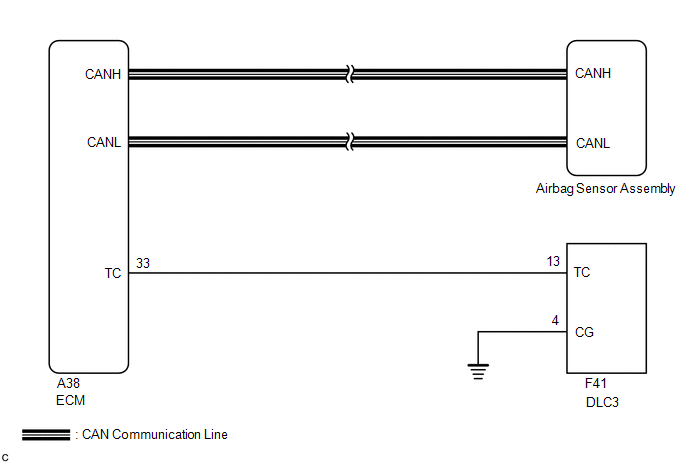
WIRING DIAGRAM
PROCEDURE
|
1. |
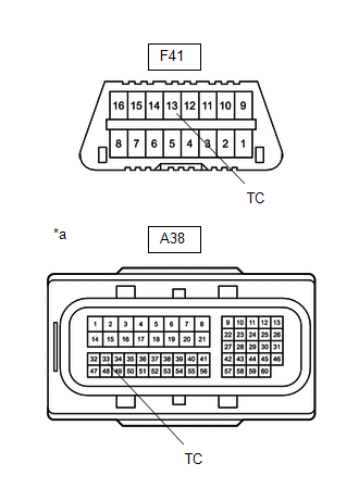
CHECK WIRE HARNESS (TC OF DLC3 - TC OF ECM) |
|
(a) Turn the ignition switch off. |
|
(b) Disconnect the connector from the ECM.
(c) Measure the resistance according to the value(s) in the table below.
Standard Resistance:
|
Tester Connection |
Condition |
Specified Condition |
|---|---|---|
|
F41-13 (TC) - A38-33 (TC) |
Always |
Below 1 Ω |
| NG | .gif) |
REPAIR OR REPLACE WIRE HARNESS |
|
.gif)
|
2. |
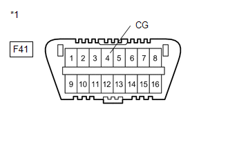
CHECK WIRE HARNESS (CG OF DLC3 - BODY GROUND) |
|
(a) Measure the resistance according to the value(s) in the table below. Standard Resistance:
|
|
| NG | |
REPAIR OR REPLACE WIRE HARNESS |
|
|
3. |
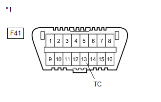
CHECK WIRE HARNESS (TC OF DLC3 - BODY GROUND) |
|
(a) Measure the resistance according to the value(s) in the table below. Standard Resistance:
|
|
| OK | |
REPLACE AIRBAG SENSOR ASSEMBLY |
.gif)
| NG | |
REPAIR OR REPLACE WIRE HARNESS OR REPLACE EACH ECU |
 Trouble in Passenger Airbag ON/OFF Indicator
DESCRIPTION
This circuit detects the airbag cut off switch cylinder sub-assembly status.
The passenger airbag ON/OFF indicator comes on to inform the driver of the instrument
panel passenger witho ...

Other materials:
Toyota CH-R Service Manual > Front Disc Brake Pad: Installation
INSTALLATION
CAUTION / NOTICE / HINT
NOTICE:
Immediately after installing the brake pads, the braking performance
may be reduced. Always perform a road test in a safe place while paying
attention to the surroundings.
Immediately after installing the front disc brake pads, the ...
Toyota CH-R Service Manual > Fuel Lid Opener Switch: Installation
INSTALLATION
PROCEDURE
1. INSTALL FUEL LID OPENER SWITCH
(a) Engage the claws to install the fuel lid opener switch as shown in the illustration.
Install in this Direction
2. INSTALL FUSE BOX OPENING COVER
Click here
3. CONNECT HOOD LOCK CONTROL LEVER ...
Toyota C-HR (AX20) 2023-2026 Owner's Manual
Toyota CH-R Owners Manual
- For safety and security
- Instrument cluster
- Operation of each component
- Driving
- Interior features
- Maintenance and care
- When trouble arises
- Vehicle specifications
- For owners
Toyota CH-R Service Manual
- Introduction
- Maintenance
- Audio / Video
- Cellular Communication
- Navigation / Multi Info Display
- Park Assist / Monitoring
- Brake (front)
- Brake (rear)
- Brake Control / Dynamic Control Systems
- Brake System (other)
- Parking Brake
- Axle And Differential
- Drive Shaft / Propeller Shaft
- K114 Cvt
- 3zr-fae Battery / Charging
- Networking
- Power Distribution
- Power Assist Systems
- Steering Column
- Steering Gear / Linkage
- Alignment / Handling Diagnosis
- Front Suspension
- Rear Suspension
- Tire / Wheel
- Tire Pressure Monitoring
- Door / Hatch
- Exterior Panels / Trim
- Horn
- Lighting (ext)
- Mirror (ext)
- Window / Glass
- Wiper / Washer
- Door Lock
- Heating / Air Conditioning
- Interior Panels / Trim
- Lighting (int)
- Meter / Gauge / Display
- Mirror (int)
- Power Outlets (int)
- Pre-collision
- Seat
- Seat Belt
- Supplemental Restraint Systems
- Theft Deterrent / Keyless Entry

0.0093