Toyota CH-R Service Manual: Extension Module Disconnected 2 (B1543)
DESCRIPTION
If the radio and display receiver assembly cannot detect the navigation ECU for a certain period of time (90 seconds) after the engine switch is turned on (ACC) and the radio and display receiver assembly confirms that the information is missing by checking past navigation ECU recognition information (registered information), this DTC will be stored.
HINT:
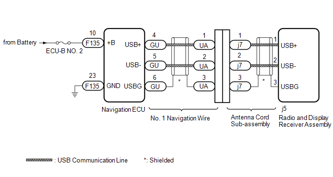
The Navigation system uses USB communication between devices. If an open, short, short to +B or short to ground occurs in the USB circuit, communication is interrupted and the Navigation system will not operate normally.
|
DTC No. |
Detection Item |
DTC Detection Condition |
Trouble Area |
|---|---|---|---|
|
B1543 |
Extension Module Disconnected 2 |
Navigation ECU disconnected |
|
HINT:
This DTC may be stored due to environmental reasons such as electrical noise or interference.
WIRING DIAGRAM
CAUTION / NOTICE / HINT
NOTICE:
- Depending on the parts that are replaced during vehicle inspection or
maintenance, performing initialization, registration or calibration may
be needed. Refer to Precaution for Navigation System.
Click here
.gif)
- Inspect the fuses for circuits related to this system before performing the following procedure.
- When replacing the radio and display receiver assembly or navigation
ECU, always replace it with a new one. If a radio and display receiver assembly
or navigation ECU which was installed to another vehicle is used, the following
may occur:
- A communication malfunction DTC may be stored.
- The radio and display receiver assembly or navigation ECU may not operate normally.
PROCEDURE
|
1. |
CHECK MAP SCREEN |
(a) Turn the engine switch on (ACC) and wait for 90 seconds.
(b) Press the "MAP" switch and check that the map screen is displayed normally.
|
Result |
Proceed to |
|---|---|
|
Map screen is displayed normally |
A |
|
Map screen is not displayed normally |
B |
HINT:
- This DTC may be stored due to environmental reasons such as electrical noise or interference.
- Clear past DTCs when the map screen is displayed normally. (Codes stored due to past environmental factors)
| A | .gif) |
USE SIMULATION METHOD TO CHECK |
|
.gif)
|
2. |
CHECK DTC |
(a) Clear the DTCs.
Body Electrical > Navigation System > Clear DTCs(b) Turn the engine switch off.
(c) Turn the engine switch on (IG) and wait for 90 seconds.
(d) Recheck for DTCs and check that no DTCs are output.
Body Electrical > Navigation System > Trouble CodesOK:
No DTCs are output.
| OK | |
USE SIMULATION METHOD TO CHECK |
|
|
3. |
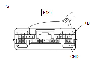
CHECK HARNESS AND CONNECTOR (NAVIGATION ECU - BATTERY AND BODY GROUND) |
|
(a) Disconnect the navigation ECU connector. |
|
(b) Measure the resistance according to the value(s) in the table below.
Standard Resistance:
|
Tester Connection |
Condition |
Specified Condition |
|---|---|---|
|
F135-23 (GND) - Body ground |
Always |
Below 1 Ω |
(c) Measure the voltage according to the value(s) in the table below.
Standard Voltage:
|
Tester Connection |
Condition |
Specified Condition |
|---|---|---|
|
F135-10 (+B) - Body ground |
Always |
11 to 14 V |
| NG | |
REPAIR OR REPLACE HARNESS OR CONNECTOR |
|
|
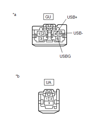
4. |
INSPECT NO. 1 NAVIGATION WIRE |
|
*a |
Front view of wire harness connector (to Navigation ECU) |
|
*b |
Front view of wire harness connector (to Antenna Cord Sub-assembly) |
(a) Disconnect the UA No. 1 navigation wire connector from the antenna cord sub-assembly.
(b) Disconnect the GU No. 1 navigation wire connector from the navigation ECU.
(c) Measure the resistance according to the value(s) in the table below.
Standard Resistance:
|
Tester Connection |
Condition |
Specified Condition |
|---|---|---|
|
GU-4 (USB+) - UA-1 |
Always |
Below 1 Ω |
|
GU-5 (USB-) - UA-2 |
Always |
Below 1 Ω |
|
GU-6 (USBG) - UA-3 |
Always |
Below 1 Ω |
| NG | |
REPAIR OR REPLACE HARNESS OR CONNECTOR |
|
|
5. |
REPLACE ANTENNA CORD SUB-ASSEMBLY |
(a) Replace the antenna cord sub-assembly with a new or known good one.
Click here
|
|
6. |
CHECK DTC |
(a) Clear the DTCs.
Body Electrical > Navigation System > Clear DTCs(b) Recheck for DTCs and check that no DTCs are output.
Body Electrical > Navigation System > Trouble CodesOK:
No DTCs are output.
| OK | |
END (ANTENNA CORD SUB-ASSEMBLY IS DEFECTIVE) |
|
|
7. |
REPLACE NAVIGATION ECU |
(a) Replace the navigation ECU with a new one.
Click here
|
|
8. |
CHECK DTC |
(a) Clear the DTCs.
Body Electrical > Navigation System > Clear DTCs(b) Turn the engine switch off.
(c) Turn the engine switch on (IG) and wait for 90 seconds.
(d) Recheck for DTCs and check that no DTCs are output.
Body Electrical > Navigation System > Trouble CodesOK:
No DTCs are output.
| OK | |
END (NAVIGATION ECU IS DEFECTIVE) |
| NG | |
REPLACE RADIO AND DISPLAY RECEIVER ASSEMBLY |
 Extension Module Malfunction 2 (B1556)
DESCRIPTION
These DTCs are stored when a malfunction occurs in the Navigation ECU.
DTC No.
Detection Item
DTC Detection Condition
Trouble Area
...
 Lost Communication with Meter (B1324)
DESCRIPTION
This DTC is stored when a communication error occurs between the radio and display
receiver assembly and combination meter assembly.
DTC No.
Detection Item
...
Other materials:
Toyota CH-R Service Manual > Continuously Variable Transaxle System: Hydraulic Test
HYDRAULIC TEST
CAUTION:
Do not perform a stall test if there are any people or objects near
the vehicle.
The vehicle could begin moving suddenly, resulting in a serious accident.
Do not perform a stall test if any wheel chocks are out of position.
The ...
Toyota CH-R Service Manual > Continuously Variable Transaxle System: Parts Location
PARTS LOCATION
ILLUSTRATION
*1
ECM
*2
SKID CONTROL ECU (BRAKE ACTUATOR ASSEMBLY)
*3
NO. 1 ENGINE ROOM RELAY BLOCK
- EFI-MAIN NO. 1 RELAY
- EFI-MAIN NO. 1 FUSE
- EFI NO. 2 FUSE
- ECU-IG2 NO. 1 FUSE
- ECU-B NO. ...
Toyota C-HR (AX20) 2023-2026 Owner's Manual
Toyota CH-R Owners Manual
- For safety and security
- Instrument cluster
- Operation of each component
- Driving
- Interior features
- Maintenance and care
- When trouble arises
- Vehicle specifications
- For owners
Toyota CH-R Service Manual
- Introduction
- Maintenance
- Audio / Video
- Cellular Communication
- Navigation / Multi Info Display
- Park Assist / Monitoring
- Brake (front)
- Brake (rear)
- Brake Control / Dynamic Control Systems
- Brake System (other)
- Parking Brake
- Axle And Differential
- Drive Shaft / Propeller Shaft
- K114 Cvt
- 3zr-fae Battery / Charging
- Networking
- Power Distribution
- Power Assist Systems
- Steering Column
- Steering Gear / Linkage
- Alignment / Handling Diagnosis
- Front Suspension
- Rear Suspension
- Tire / Wheel
- Tire Pressure Monitoring
- Door / Hatch
- Exterior Panels / Trim
- Horn
- Lighting (ext)
- Mirror (ext)
- Window / Glass
- Wiper / Washer
- Door Lock
- Heating / Air Conditioning
- Interior Panels / Trim
- Lighting (int)
- Meter / Gauge / Display
- Mirror (int)
- Power Outlets (int)
- Pre-collision
- Seat
- Seat Belt
- Supplemental Restraint Systems
- Theft Deterrent / Keyless Entry

0.0094