Toyota CH-R Service Manual: Trouble in Passenger Airbag ON/OFF Indicator
DESCRIPTION
This circuit detects the airbag cut off switch cylinder sub-assembly status.
The passenger airbag ON/OFF indicator comes on to inform the driver of the instrument panel passenger without door airbag assembly status (activated or deactivated).
HINT:
Approximately 6 seconds after the ignition switch is turned ON, the passenger airbag ON/OFF indicator will indicate ON/OFF depending on the following conditions.
|
Airbag Cut Off Switch Cylinder Sub-assembly |
Passenger Airbag ON/OFF Indicator |
SRS Warning Light |
|
|---|---|---|---|
|
ON Indicator |
OFF Indicator |
||
|
ON |
ON |
OFF |
OFF |
|
OFF |
OFF |
ON |
OFF |
|
Switch failure |
OFF |
ON |
ON |
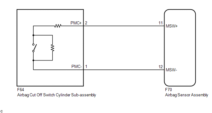
WIRING DIAGRAM
CAUTION / NOTICE / HINT
NOTICE:
After turning the ignition switch off, waiting time may be required before disconnecting the cable from the negative (-) battery terminal. Therefore, make sure to read the disconnecting the cable from the negative (-) battery terminal notices before proceeding with work.
Click here .gif)
HINT:
Terminals F70-11 (MSW+) and F70-12 (MSW-) of the instrument panel wire in this circuit have an activation prevention mechanism.
This mechanism can be used to check for an open circuit in the wire harness. When performing other checks (check for short, short to ground or short to B+), this mechanism should be released.
PROCEDURE
|
1. |
CHECK SRS WARNING LIGHT |
(a) Turn the ignition switch ON, and check the SRS warning light condition.
OK:
After the primary check period, the SRS warning light goes off.
HINT:
- If the SRS warning light is on when this malfunction occurs, a DTC is stored. Troubleshoot for the stored DTC.
- The primary check period is approximately 6 seconds after the ignition switch is turned ON.
| NG | .gif) |
GO TO DIAGNOSTIC TROUBLE CODE CHART |
|
.gif)
|
2. |
CHECK CONNECTORS |
(a) Turn the ignition switch off.
(b) Disconnect the cable from the negative (-) battery terminal.
CAUTION:
Wait at least 90 seconds after disconnecting the cable from the negative (-) battery terminal to disable the SRS system.
(c) Check that the connectors are properly connected to the airbag sensor assembly and airbag cut off switch cylinder sub-assembly.
OK:
The connectors are properly connected.
HINT:
If the connectors are not properly connected, reconnect the connectors and proceed to the next inspection.
(d) Disconnect the connectors from the airbag sensor assembly and airbag cut off switch cylinder sub-assembly.
(e) Check that the terminals of the connectors are not deformed or damaged.
OK:
The terminals are not deformed or damaged.
(f) Check that the short springs of the activation prevention mechanism of the instrument panel wire connector are not deformed or damaged.
OK:
The short springs are not deformed or damaged.
| NG | |
REPLACE INSTRUMENT PANEL WIRE |
|
|
3. |
CHECK INSTRUMENT PANEL WIRE (OPEN) |
|
(a) Measure the resistance according to the value(s) in the table below. Standard Resistance:
|
|
.png)
| NG | |
REPLACE INSTRUMENT PANEL WIRE |
|
|
4. |
CHECK INSTRUMENT PANEL WIRE (SHORT) |
|
(a) Release the activation prevention mechanism built into connector B. Click here |
|
(b) Measure the resistance according to the value(s) in the table below.
Standard Resistance:
|
Tester Connection |
Condition |
Specified Condition |
|---|---|---|
|
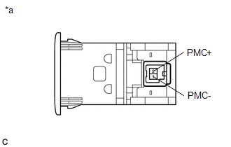
F64-2 (PMC+) - F64-1 (PMC-) |
Always |
1 MΩ or higher |
| NG | |
REPLACE INSTRUMENT PANEL WIRE |
|
|
5. |
CHECK INSTRUMENT PANEL WIRE (SHORT TO B+) |
|
(a) Connect the cable to the negative (-) battery terminal. |
|
(b) Turn the ignition switch ON.
(c) Measure the voltage according to the value(s) in the table below.
Standard Voltage:
|
Tester Connection |
Switch Condition |
Specified Condition |
|---|---|---|
|
F64-2 (PMC+) - Body ground |
Ignition switch ON |
Below 1 V |
|
F64-1 (PMC-) - Body ground |
Ignition switch ON |
Below 1 V |
(d) Turn the ignition switch off.
(e) Disconnect the cable from the negative (-) battery terminal.
CAUTION:
Wait at least 90 seconds after disconnecting the cable from the negative (-) battery terminal to disable the SRS system.
| NG | |
REPLACE INSTRUMENT PANEL WIRE |
|
|
6. |
CHECK INSTRUMENT PANEL WIRE (SHORT TO GROUND) |
|
(a) Measure the resistance according to the value(s) in the table below. Standard Resistance:
|
|
(b) Restore the released activation prevention mechanism of connector B to the original condition.
| NG | |
REPLACE INSTRUMENT PANEL WIRE |
|
|
7. |
CHECK AIRBAG CUT OFF SWITCH CYLINDER SUB-ASSEMBLY |
|
(a) Measure the resistance according to the value(s) in the table below. Standard Resistance:
|
|
| OK | |
REPLACE AIRBAG SENSOR ASSEMBLY |
| NG | |
REPLACE AIRBAG CUT OFF SWITCH CYLINDER SUB-ASSEMBLY |
 SRS Warning Light does not Come ON
DESCRIPTION
The SRS warning light is located in the combination meter assembly.
When the SRS is normal, the SRS warning light comes on for approximately 6 seconds
after the ignition switch is turn ...
 TC and CG Terminal Circuit
DESCRIPTION
DTC output mode is set by connecting terminals TC and CG of the DLC3.
DTCs are displayed by blinking of the SRS warning light.
HINT:
When multiple warning lights in the combina ...
Other materials:
Toyota CH-R Service Manual > Rear Suspension Member: Components
COMPONENTS
ILLUSTRATION
*1
TAIL EXHAUST PIPE ASSEMBLY
*2
COMPRESSION SPRING
N*m (kgf*cm, ft.*lbf): Specified torque
-
-
ILLUSTRATION
*1
REAR FLEXIBLE HOSE LH
...
Toyota CH-R Service Manual > Air Conditioning System(for Automatic Air Conditioning System With Top-mounted
Air Conditioner Pressure Sensor): IG Power Source Circuit
DESCRIPTION
Power source voltage is supplied to the air conditioning amplifier assembly when
the ignition switch is turned ON. This power is used for operating the air conditioning
amplifier assembly, servo motors, etc.
WIRING DIAGRAM
CAUTION / NOTICE / HINT
NOTICE:
Inspect the fuses for ...
Toyota C-HR (AX20) 2023-2026 Owner's Manual
Toyota CH-R Owners Manual
- For safety and security
- Instrument cluster
- Operation of each component
- Driving
- Interior features
- Maintenance and care
- When trouble arises
- Vehicle specifications
- For owners
Toyota CH-R Service Manual
- Introduction
- Maintenance
- Audio / Video
- Cellular Communication
- Navigation / Multi Info Display
- Park Assist / Monitoring
- Brake (front)
- Brake (rear)
- Brake Control / Dynamic Control Systems
- Brake System (other)
- Parking Brake
- Axle And Differential
- Drive Shaft / Propeller Shaft
- K114 Cvt
- 3zr-fae Battery / Charging
- Networking
- Power Distribution
- Power Assist Systems
- Steering Column
- Steering Gear / Linkage
- Alignment / Handling Diagnosis
- Front Suspension
- Rear Suspension
- Tire / Wheel
- Tire Pressure Monitoring
- Door / Hatch
- Exterior Panels / Trim
- Horn
- Lighting (ext)
- Mirror (ext)
- Window / Glass
- Wiper / Washer
- Door Lock
- Heating / Air Conditioning
- Interior Panels / Trim
- Lighting (int)
- Meter / Gauge / Display
- Mirror (int)
- Power Outlets (int)
- Pre-collision
- Seat
- Seat Belt
- Supplemental Restraint Systems
- Theft Deterrent / Keyless Entry

0.0079