Toyota CH-R Service Manual: Television Camera
Components
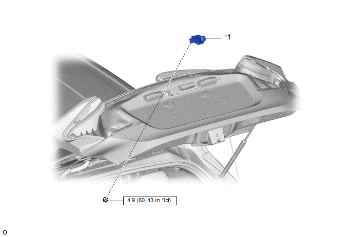
COMPONENTS
ILLUSTRATION
|
*1 |
REAR TELEVISION CAMERA ASSEMBLY |
- |
- |
.png) |
N*m (kgf*cm, ft.*lbf): Specified torque |
- |
- |
Removal
REMOVAL
PROCEDURE
1. REMOVE BACK DOOR OUTSIDE GARNISH
Click here
.gif)
2. REMOVE REAR TELEVISION CAMERA ASSEMBLY
|
(a) Disconnect the connector. |
|
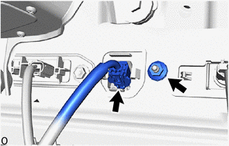
(b) Remove the nut.
|
(c) Disengage the claws to remove the rear television camera assembly. |
|
Installation
INSTALLATION
PROCEDURE
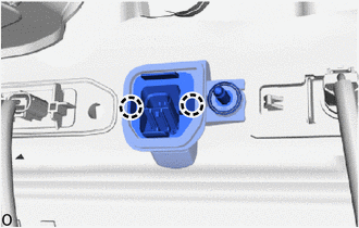
1. INSTALL REAR TELEVISION CAMERA ASSEMBLY
(a) Engage the claws to temporarily install the rear television camera assembly.
(b) Install the nut.
Torque:
4.9 N·m {50 kgf·cm, 43 in·lbf}
(c) Connect the connector.
2. INSTALL BACK DOOR GARNISH OUTSIDE
Click here
.gif)
 Image from Camera for Rear View Monitor is Abnormal
DESCRIPTION
The video signal of the rear television camera assembly is transmitted to the
radio and display receiver assembly.
WIRING DIAGRAM
CAUTION / NOTICE / HINT
NOTICE:
When repl ...
 Brake (front)
...
Other materials:
Toyota CH-R Service Manual > Theft Deterrent System: Parts Location
PARTS LOCATION
ILLUSTRATION
*1
HOOD COURTESY SWITCH
*2
LOW PITCHED HORN ASSEMBLY
*3
HORN RELAY
*4
SECURITY HORN ASSEMBLY
*5
HOOD LOCK ASSEMBLY
*6
NO. 1 ...
Toyota CH-R Service Manual > Audio And Visual System(for Radio And Display Type): Telematics Transceiver Disconnected (B15DB)
DESCRIPTION
If the radio and display receiver assembly cannot detect the DCM (telematics
transceiver) for a certain period of time (90 seconds) after the ignition switch
is turned on (ACC) and the radio and display receiver assembly confirms that the
information is missing by checking past DC ...
Toyota C-HR (AX20) 2023-2026 Owner's Manual
Toyota CH-R Owners Manual
- For safety and security
- Instrument cluster
- Operation of each component
- Driving
- Interior features
- Maintenance and care
- When trouble arises
- Vehicle specifications
- For owners
Toyota CH-R Service Manual
- Introduction
- Maintenance
- Audio / Video
- Cellular Communication
- Navigation / Multi Info Display
- Park Assist / Monitoring
- Brake (front)
- Brake (rear)
- Brake Control / Dynamic Control Systems
- Brake System (other)
- Parking Brake
- Axle And Differential
- Drive Shaft / Propeller Shaft
- K114 Cvt
- 3zr-fae Battery / Charging
- Networking
- Power Distribution
- Power Assist Systems
- Steering Column
- Steering Gear / Linkage
- Alignment / Handling Diagnosis
- Front Suspension
- Rear Suspension
- Tire / Wheel
- Tire Pressure Monitoring
- Door / Hatch
- Exterior Panels / Trim
- Horn
- Lighting (ext)
- Mirror (ext)
- Window / Glass
- Wiper / Washer
- Door Lock
- Heating / Air Conditioning
- Interior Panels / Trim
- Lighting (int)
- Meter / Gauge / Display
- Mirror (int)
- Power Outlets (int)
- Pre-collision
- Seat
- Seat Belt
- Supplemental Restraint Systems
- Theft Deterrent / Keyless Entry

0.008