Toyota CH-R Service Manual: Installation
INSTALLATION
PROCEDURE
1. INSTALL TIE ROD END SUB-ASSEMBLY LH
|
(a) Install the lock nut and tie rod end sub-assembly LH to the steering gear assembly until the matchmarks are aligned. HINT: After adjusting the toe-in, tighten the lock nut. |
|
.png)
2. INSTALL TIE ROD END SUB-ASSEMBLY RH
HINT:
Perform the same procedure as for the LH side.
3. INSTALL STEERING LINK ASSEMBLY
(a) Insert the steering link assembly as shown in the illustration.
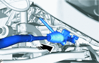
.png) |
Install in this Direction |
|
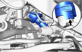
(b) Align the protrusion of the steering link assembly with the hole of the No. 1 steering column hole cover sub-assembly, and install the No. 1 steering column hole cover sub-assembly to the steering link assembly. HINT: Check that the No. 1 steering column hole cover sub-assembly is securely installed. |
|
(c) Install the steering link assembly to the front suspension crossmember sub-assembly with the 2 bolts and 2 new nuts.
Torque:
133 N·m {1356 kgf·cm, 98 ft·lbf}
NOTICE:
- Because the nut has its own stopper, do not turn the nut. Tighten the bolt with the nut secured.
- Make sure to tighten the bolts starting from the left side of the vehicle.
(d) Install the wire harness clamp bracket to the front suspension crossmember sub-assembly with the bolt.
(e) Connect the connector.
4. CONNECT TIE ROD END SUB-ASSEMBLY LH
|
(a) Connect the tie rod end sub-assembly LH to the steering knuckle LH with the nut. Torque: 49 N·m {500 kgf·cm, 36 ft·lbf} NOTICE:
|
|
.png)
(b) Install a new cotter pin.
5. CONNECT TIE ROD END SUB-ASSEMBLY RH
HINT:
Perform the same procedure as for the LH side.
6. CONNECT NO. 1 STEERING COLUMN HOLE COVER SUB-ASSEMBLY
|
(a) Engage the clip (B) to the vehicle body. |
|
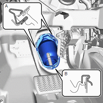
(b) Engage the clip (A) to install the No. 1 steering column hole cover sub-assembly to the vehicle body.
NOTICE:
Be careful not to damage the lip of the No. 1 steering column hole cover sub-assembly.
7. CONNECT NO. 2 STEERING INTERMEDIATE SHAFT ASSEMBLY
Click here
.gif)
8. INSTALL COLUMN HOLE COVER SILENCER SHEET
Click here
9. INSTALL FRONT WHEELS
Click here
10. STABILIZE SUSPENSION
Click here
11. INSPECT AND ADJUST FRONT WHEEL ALIGNMENT
Click here
 Inspection
INSPECTION
PROCEDURE
1. INSPECT TIE ROD END SUB-ASSEMBLY LH
(a) Secure the tie rod end sub-assembly LH in a vise between aluminum
plates.
NOTICE:
Do not overtighten the vise.
...
 Reassembly
REASSEMBLY
PROCEDURE
1. INSTALL NO. 2 STEERING RACK BOOT
(a) Apply lithium soap base glycol grease to the inside of the small
opening of a new No. 2 steering rack boot.
...
Other materials:
Toyota CH-R Owners Manual > Using the other interior features: Other interior features
Sun visors
To set the visor in the forward position, flip it down.
To set the visor in the side position, flip down, unhook, and swing it to
the side.
Vanity mirrors
Slide the cover to open.
The light turns on when the cover is opened. (if equipped)
Clock
The clock can be adj ...
Toyota CH-R Service Manual > Smart Key System(for Entry Function): Back Door Entry Lock Function does not Operate
DESCRIPTION
If the entry lock function does not operate for the back door only, but the entry
unlock function operates, the request code is being transmitted properly from the
back door. In this case, there may be a problem related to the lock switch (connection
between the back door opener s ...
Toyota C-HR (AX20) 2023-2026 Owner's Manual
Toyota CH-R Owners Manual
- For safety and security
- Instrument cluster
- Operation of each component
- Driving
- Interior features
- Maintenance and care
- When trouble arises
- Vehicle specifications
- For owners
Toyota CH-R Service Manual
- Introduction
- Maintenance
- Audio / Video
- Cellular Communication
- Navigation / Multi Info Display
- Park Assist / Monitoring
- Brake (front)
- Brake (rear)
- Brake Control / Dynamic Control Systems
- Brake System (other)
- Parking Brake
- Axle And Differential
- Drive Shaft / Propeller Shaft
- K114 Cvt
- 3zr-fae Battery / Charging
- Networking
- Power Distribution
- Power Assist Systems
- Steering Column
- Steering Gear / Linkage
- Alignment / Handling Diagnosis
- Front Suspension
- Rear Suspension
- Tire / Wheel
- Tire Pressure Monitoring
- Door / Hatch
- Exterior Panels / Trim
- Horn
- Lighting (ext)
- Mirror (ext)
- Window / Glass
- Wiper / Washer
- Door Lock
- Heating / Air Conditioning
- Interior Panels / Trim
- Lighting (int)
- Meter / Gauge / Display
- Mirror (int)
- Power Outlets (int)
- Pre-collision
- Seat
- Seat Belt
- Supplemental Restraint Systems
- Theft Deterrent / Keyless Entry

0.0078