Toyota CH-R Service Manual: Reassembly
REASSEMBLY
PROCEDURE
1. INSTALL NO. 2 STEERING RACK BOOT
|
(a) Apply lithium soap base glycol grease to the inside of the small opening of a new No. 2 steering rack boot. |
|
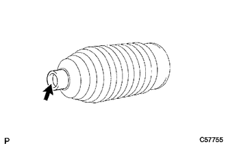
(b) Install the No. 2 steering rack boot to the groove on the rack housing.
NOTICE:
- Be careful not to damage or twist the No. 2 steering rack boot.
- Make sure that the No. 2 steering rack boot is free of rust and foreign matter.
2. INSTALL NO. 1 STEERING RACK BOOT
HINT:
Perform the same procedure as for the No. 2 steering rack boot.
3. INSTALL STEERING RACK BOOT CLAMP (for LH Side)
|
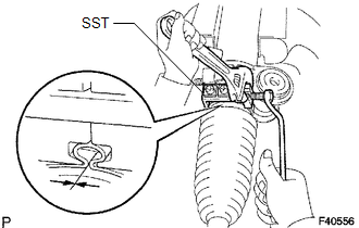
(a) Using SST, install a new steering rack boot clamp as shown in the illustration. SST: 09521-24010 Clearance: 3.0 mm (0.118 in.) or less NOTICE: Be careful not to damage the No. 2 steering rack boot. |
|
4. INSTALL STEERING RACK BOOT CLAMP (for RH Side)
HINT:
Perform the same procedure as for the LH side.
5. INSTALL STEERING RACK BOOT CLIP (for LH Side)
(a) Using pliers, install the steering rack boot clip.
6. INSTALL STEERING RACK BOOT CLIP (for RH Side)
HINT:
Perform the same procedure as for the LH side.
7. INSPECT STEERING GEAR ASSEMBLY
|
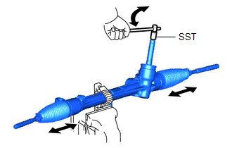
(a) Using SST, rotate the pinion shaft to see if both the left and the right steering rack boots expand and contract smoothly. SST: 09616-00020 If the left and right steering rack boots do not expand and contract smoothly, use new steering rack boot retainers and reinstall the steering rack boots. |
|
 Installation
INSTALLATION
PROCEDURE
1. INSTALL TIE ROD END SUB-ASSEMBLY LH
(a) Install the lock nut and tie rod end sub-assembly LH to the steering
gear assembly until the matchmarks are aligned. ...

Other materials:
Toyota CH-R Service Manual > Power Steering System: How To Proceed With Troubleshooting
CAUTION / NOTICE / HINT
HINT:
Use these procedures to troubleshoot the power steering system.
*: Use the Techstream.
PROCEDURE
1.
VEHICLE BROUGHT TO WORKSHOP
NEXT
2.
...
Toyota CH-R Service Manual > Navigation System: Noise Occurs or Sound Skips when Portable Player Plays
CAUTION / NOTICE / HINT
HINT:
Perform this check with the portable player volume set at an appropriate
level.
Make sure that there are no obstructions between the portable player
and the radio and display receiver assembly that may block signals, and
that the portable playe ...
Toyota C-HR (AX20) 2023-2026 Owner's Manual
Toyota CH-R Owners Manual
- For safety and security
- Instrument cluster
- Operation of each component
- Driving
- Interior features
- Maintenance and care
- When trouble arises
- Vehicle specifications
- For owners
Toyota CH-R Service Manual
- Introduction
- Maintenance
- Audio / Video
- Cellular Communication
- Navigation / Multi Info Display
- Park Assist / Monitoring
- Brake (front)
- Brake (rear)
- Brake Control / Dynamic Control Systems
- Brake System (other)
- Parking Brake
- Axle And Differential
- Drive Shaft / Propeller Shaft
- K114 Cvt
- 3zr-fae Battery / Charging
- Networking
- Power Distribution
- Power Assist Systems
- Steering Column
- Steering Gear / Linkage
- Alignment / Handling Diagnosis
- Front Suspension
- Rear Suspension
- Tire / Wheel
- Tire Pressure Monitoring
- Door / Hatch
- Exterior Panels / Trim
- Horn
- Lighting (ext)
- Mirror (ext)
- Window / Glass
- Wiper / Washer
- Door Lock
- Heating / Air Conditioning
- Interior Panels / Trim
- Lighting (int)
- Meter / Gauge / Display
- Mirror (int)
- Power Outlets (int)
- Pre-collision
- Seat
- Seat Belt
- Supplemental Restraint Systems
- Theft Deterrent / Keyless Entry

0.0081