Toyota CH-R Service Manual: Removal
REMOVAL
CAUTION / NOTICE / HINT
The necessary procedures (adjustment, calibration, initialization, or registration) that must be performed after parts are removed, installed, or replaced during the continuously variable transaxle assembly removal/installation are shown below.
Necessary Procedure After Parts Removed/Installed/Replaced|
Replacement Part or Procedure |
Necessary Procedure |
Effect/Inoperative when not Performed |
Link |
|---|---|---|---|
|
Disconnect cable from negative battery terminal |
Initialize back door lock |
Power door lock control system |
|
|
Memorize steering angle neutral point |
Lane departure alert system (w/ Steering Control) |
|
|
|
Pre-collision system |
|||
|
Inspection After Repair |
|
|
|
Replacement of CVT fluid |
ATF thermal degradation estimate reset |
The value of the Data List item "ATF Thermal Degradation Estimate" is not estimated correctly |
|
|
Replacement of continuously variable transaxle assembly |
Perform the following procedures in the order shown:
|
Deterioration of fuel efficiency |
|
|
Front wheel alignment adjustment |
Perform the following procedures in the order shown:
|
|
|
CAUTION:
- Because the continuously variable transaxle assembly is extremely heavy,
make sure to follow the work procedures described in the repair manual.
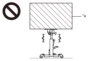
*a
Heavy object exceeding the capacity of the transmission jack
- If work is not performed according to the procedures described in the repair manual, there is a danger that the transmission jack could drop and components could fall down.
- When the engine is hot, do not touch high-temperature areas such as
the engine or exhaust pipe.
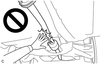
- Touching high-temperature areas such as the engine and exhaust pipe could result in burns.
PROCEDURE
1. REMOVE FLYWHEEL HOUSING UNDER COVER
|
(a) Remove the flywheel housing under cover. |
|
2. REMOVE DRIVE PLATE AND TORQUE CONVERTER ASSEMBLY SETTING BOLT
|
(a) Turn the crankshaft to gain access to the 6 drive plate and torque converter assembly setting bolts and remove each drive plate and torque converter assembly setting bolt while holding the crankshaft pulley bolt with a wrench. HINT: There will be one black colored drive plate and torque converter assembly setting bolt. |
|
3. REMOVE ENGINE ASSEMBLY WITH TRANSAXLE
Click here
.gif)
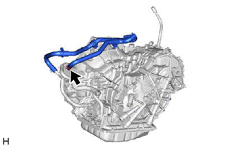
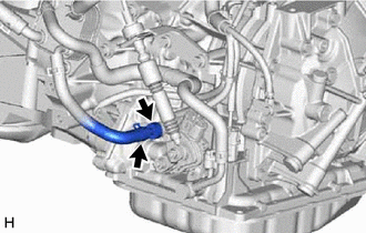
4. DISCONNECT NO. 3 WATER BY-PASS HOSE
|
(a) Slide the clip and disconnect the No. 3 water by-pass hose from the oil cooler. |
|
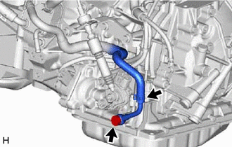
5. DISCONNECT NO. 5 WATER BY-PASS HOSE
|
(a) Slide the hose clip and disconnect the No. 5 water by-pass hose from the transmission oil cooler. |
|
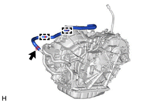
(b) Disengage the 2 clamps to disconnect the No. 5 water by-pass hose from the continuously variable transaxle assembly.
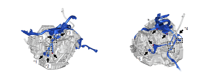
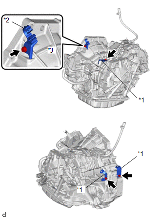
6. DISCONNECT ENGINE WIRE
(a) Disconnect the park/neutral position switch connector.
|
*1 |
Park/Neutral Position Switch Connector |
*2 |
Transmission Wire Connector |
|
*3 |
Transmission Revolution Sensor (NIN) Connector |
*4 |
Transmission Revolution Sensor (NOUT) Connector |
|
*5 |
Transmission Revolution Sensor (NT) Connector |
*6 |
Oil Pressure Sensor Connector |
(b) Disconnect the transmission wire connector.
(c) Disconnect the transmission revolution sensor (NIN) connector.
(d) Disconnect the transmission revolution sensor (NT) connector.
(e) Disconnect the transmission revolution sensor (NOUT) connector.
(f) Disconnect the oil pressure sensor connector.
(g) Remove the 3 bolts and nut to disconnect the engine wire from the continuously variable transaxle assembly.
(h) Disengage the 5 clamps to disconnect the engine wire from the continuously variable transaxle assembly.
|
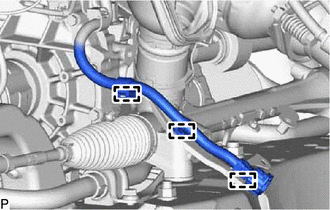
(i) Disengage the 3 clamps to disconnect the engine wire from the front suspension crossmember sub-assembly. |
|
7. REMOVE STARTER ASSEMBLY
Click here
8. REMOVE FLYWHEEL HOUSING SIDE COVER
Click here
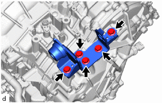
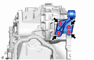
9. REMOVE TRANSVERSE ENGINE ENGINE MOUNTING BRACKET
|
(a) Remove the 5 bolts and transverse engine engine mounting bracket from the continuously variable transaxle assembly. |
|
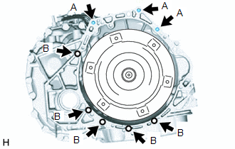
10. REMOVE ENGINE ASSEMBLY
|
(a) Remove the 8 bolts and engine assembly from the continuously variable transaxle assembly. NOTICE: To prevent damage to the 2 knock pins, do not pry between the continuously variable transaxle assembly and engine assembly. HINT:
|
|
11. REMOVE TORQUE CONVERTER ASSEMBLY
(a) Remove the torque converter assembly from the continuously variable transaxle assembly.
NOTICE:
Remove the torque converter assembly from the input shaft horizontally.
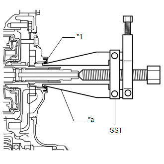
12. REMOVE CVT OIL PUMP TYPE T OIL SEAL
CAUTION:
- Do not remove the front oil pump assembly from the continuously variable transaxle assembly main body, as there is a possibility of the entry of dust and foreign matter.
- Clean the work area, the tools to be used, and other equipment, etc. thoroughly before the operation, as there is the possibility that a continuously variable transaxle assembly malfunction, which may prevent the vehicle from being driven, may occur if dust or fine foreign matter enters the continuously variable transaxle assembly.
- Do not use cotton work gloves, cloths, paper towels, etc. that may produce lint, dust or foreign matter.
- Perform the operation as quickly as possible, as dust and foreign matter may enter the continuously variable transaxle assembly while the torque converter assembly is not attached to it.
- Do not use an air gun until the torque converter assembly has been installed, as it may cause dust and foreign matter to be stirred up.
(a) Clean the tips of both the claws of SST and the center bolt.
SST: 09308-10010
|
(b) Using SST, remove the CVT oil pump type T oil seal from the continuously variable transaxle assembly. NOTICE: Pay attention to the angle of the claws of SST when opening them, and ensure that they do not come into contact with the oil pump housing, as there is the possibility that metal particles may be produced if they do. |
|
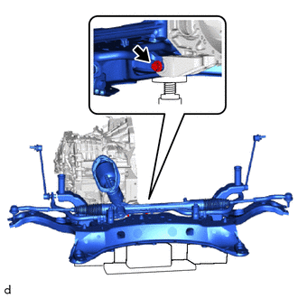
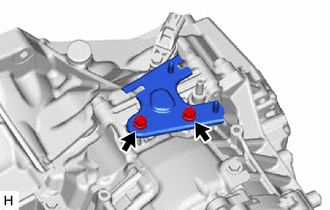
13. REMOVE FRONT SUSPENSION CROSSMEMBER SUB-ASSEMBLY
|
(a) Remove the bolt and front suspension crossmember sub-assembly from the No. 2 engine moving control rod. |
|
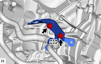
14. REMOVE NO. 2 ENGINE MOVING CONTROL ROD
|
(a) Remove the 4 bolts and No. 2 engine moving control rod from the continuously variable transaxle assembly. |
|
15. REMOVE NO. 1 TRANSMISSION CONTROL CABLE BRACKET
|
(a) Disengage the clamp from the No. 1 transmission control cable bracket. |
|
(b) Remove the 2 bolts and No. 1 transmission control cable bracket from the continuously variable transaxle assembly.
16. REMOVE TRANSMISSION CONTROL CABLE SUPPORT
|
(a) Remove the 2 bolts and transmission control cable support from the continuously variable transaxle assembly. |
|
17. REMOVE WIRE HARNESS CLAMP BRACKET
|
(a) Remove the bolt and water hose clamp bracket from the continuously variable transaxle assembly. |
|
(b) Remove the water by-pass hose clamp from the water hose clamp bracket.
(c) Remove the 3 bolts and 3 wire harness clamp brackets from the continuously variable transaxle assembly.
18. REMOVE TUBE CONNECTOR
|
(a) Slide the clip and disconnect the No. 1 transmission oil cooler hose from the tube connector. NOTICE: Do not damage the coating of the hose insertion part of the tube connector. |
|
(b) Remove the tube connector from the continuously variable transaxle assembly.
(c) Remove the O-ring from the tube connector.
19. REMOVE OIL COOLER ELBOW SUB-ASSEMBLY
|
(a) Slide the clip and disconnect the No. 2 transmission oil cooler hose from the oil cooler elbow sub-assembly. NOTICE: Do not damage the coating of the hose insertion part of the oil cooler elbow sub-assembly. |
|
(b) Remove the union bolt, oil cooler elbow sub-assembly and gasket from the continuously variable transaxle assembly.
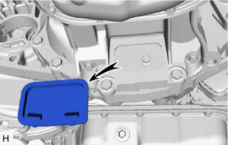
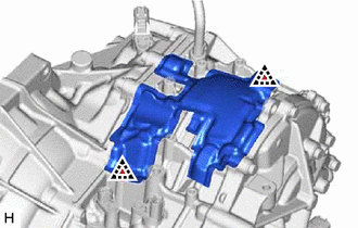
20. REMOVE AUTOMATIC TRANSMISSION CASE COVER
|
(a) Remove the 2 clips and automatic transmission case cover from the continuously variable transaxle assembly. |
|
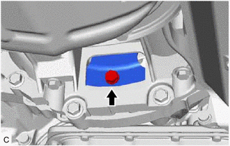
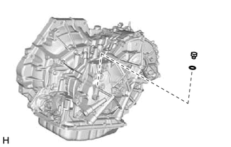
21. REMOVE STRAIGHT SCREW PLUG
HINT:
Perform this procedure only when replacement of the straight screw plug is necessary.
|
(a) Remove the straight screw plug and gasket from the continuously variable transaxle assembly. |
|
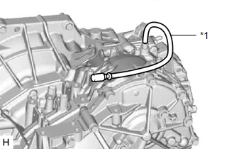
22. REMOVE TRANSMISSION BREATHER HOSE SUB-ASSEMBLY
HINT:
Perform this procedure only when replacement of the transmission breather hose sub-assembly is necessary.
|
(a) Remove the transmission breather hose sub-assembly from the continuously variable transaxle assembly. |
|
|
(b) Remove the No. 1 breather plug (CVT) and No. 2 breather plug (CVT) from the breather plug hose. |
|
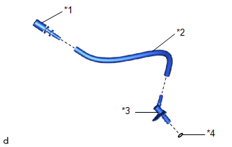
(c) Remove the O-ring from the breather plug.
23. INSPECT TORQUE CONVERTER ASSEMBLY
Click here
24. INSPECT DRIVE PLATE AND RING GEAR SUB-ASSEMBLY
Click here
 Components
COMPONENTS
ILLUSTRATION
*1
ENGINE WIRE
*2
FRONT SUSPENSION CROSSMEMBER SUB-ASSEMBLY
*3
NO. 2 ENGINE MOVING CONTROL ROD
...
 Installation
INSTALLATION
CAUTION / NOTICE / HINT
CAUTION:
The engine assembly with continuously variable transaxle assembly is very heavy.
Be sure to follow the procedure described in the repair manual, or t ...
Other materials:
Toyota CH-R Service Manual > Vehicle Stability Control System: Slip Indicator Light does not Come ON
DESCRIPTION
The skid control ECU (brake actuator assembly) is connected to the combination
meter assembly via CAN communication.
CAUTION / NOTICE / HINT
NOTICE:
When replacing the skid control ECU (brake actuator assembly), perform system
variant learning.
Click here
PROCEDURE
...
Toyota CH-R Service Manual > Airbag System: Occupant Classification System Malfunction (B1650/32,B165A/32)
DESCRIPTION
The airbag sensor assembly and occupant detection ECU communicate via CAN communication.
When the occupant detection ECU stores DTC B1771, B1780, B1782, B1795, B1798,
B1799, U0125 or U0129, the airbag sensor assembly receives this information and
stores DTC B1650/32.
When the occu ...
Toyota C-HR (AX20) 2023-2026 Owner's Manual
Toyota CH-R Owners Manual
- For safety and security
- Instrument cluster
- Operation of each component
- Driving
- Interior features
- Maintenance and care
- When trouble arises
- Vehicle specifications
- For owners
Toyota CH-R Service Manual
- Introduction
- Maintenance
- Audio / Video
- Cellular Communication
- Navigation / Multi Info Display
- Park Assist / Monitoring
- Brake (front)
- Brake (rear)
- Brake Control / Dynamic Control Systems
- Brake System (other)
- Parking Brake
- Axle And Differential
- Drive Shaft / Propeller Shaft
- K114 Cvt
- 3zr-fae Battery / Charging
- Networking
- Power Distribution
- Power Assist Systems
- Steering Column
- Steering Gear / Linkage
- Alignment / Handling Diagnosis
- Front Suspension
- Rear Suspension
- Tire / Wheel
- Tire Pressure Monitoring
- Door / Hatch
- Exterior Panels / Trim
- Horn
- Lighting (ext)
- Mirror (ext)
- Window / Glass
- Wiper / Washer
- Door Lock
- Heating / Air Conditioning
- Interior Panels / Trim
- Lighting (int)
- Meter / Gauge / Display
- Mirror (int)
- Power Outlets (int)
- Pre-collision
- Seat
- Seat Belt
- Supplemental Restraint Systems
- Theft Deterrent / Keyless Entry

0.0073