Toyota CH-R Service Manual: Installation
INSTALLATION
CAUTION / NOTICE / HINT
CAUTION:
The engine assembly with continuously variable transaxle assembly is very heavy. Be sure to follow the procedure described in the repair manual, or the engine lifter may suddenly drop.
PROCEDURE
1. INSTALL TRANSMISSION BREATHER HOSE SUB-ASSEMBLY
HINT:
Perform this procedure only when replacement of the transmission breather hose sub-assembly is necessary.
(a) Apply Toyota Genuine CVT fluid FE to a new O-ring, and install it to the No. 2 breather plug (CVT).
NOTICE:
Be careful not to damage or twist the O-ring.
(b) Install the No. 1 breather plug (CVT) and No. 2 breather plug (CVT) to the breather plug hose.
(c) Install the transmission breather hose sub-assembly to the continuously variable transaxle assembly.
2. INSTALL STRAIGHT SCREW PLUG
HINT:
Perform this procedure only when replacement of the straight screw plug is necessary.
(a) Install a new gasket and the straight screw plug to the continuously variable transaxle assembly.
Torque:
16.2 N·m {165 kgf·cm, 12 ft·lbf}
3. INSTALL AUTOMATIC TRANSMISSION CASE COVER
(a) Install the automatic transmission case cover to the continuously variable transaxle assembly with the 2 clips.
4. INSTALL OIL COOLER ELBOW SUB-ASSEMBLY
(a) Install a new gasket and oil cooler elbow sub-assembly to the continuously variable transaxle assembly with the union bolt.
Torque:
22.6 N·m {230 kgf·cm, 17 ft·lbf}
NOTICE:
- Make sure to insert the painted end (white) of the No. 2 transmission oil cooler hose up to the spool fitting of the oil cooler elbow sub-assembly so that the marking is facing the front of the vehicle.
- Make sure to clean and degrease the insertion part of the No. 2 transmission oil cooler hose of the oil cooler elbow sub-assembly.
(b) Install the No. 2 transmission oil cooler hose to the oil cooler elbow sub-assembly and slide the clip to secure it.
5. INSTALL TUBE CONNECTOR
(a) Install a new O-ring to the tube connector.
(b) Install the tube connector to the continuously variable transaxle assembly.
Torque:
27 N·m {275 kgf·cm, 20 ft·lbf}
(c) Install the No. 1 transmission oil cooler hose to the tube connector and slide the clip to secure it.
6. INSTALL WIRE HARNESS CLAMP BRACKET
|
(a) Install the 3 wire harness clamp brackets to the continuously variable transaxle assembly with the 3 bolts. Torque: 8.0 N·m {82 kgf·cm, 71 in·lbf} |
|
(b) Install the water by-pass hose clamp to the water hose clamp bracket.
(c) Install the water hose clamp bracket to the continuously variable transaxle assembly with the bolt.
Torque:
10 N·m {102 kgf·cm, 7 ft·lbf}
7. INSTALL TRANSMISSION CONTROL CABLE SUPPORT
(a) Install the transmission control cable support to the continuously variable transaxle assembly with the 2 bolts.
Torque:
8.0 N·m {82 kgf·cm, 71 in·lbf}
8. INSTALL NO. 1 TRANSMISSION CONTROL CABLE BRACKET
(a) Install the No. 1 transmission control cable bracket to the continuously variable transaxle assembly with the 2 bolts.
Torque:
12 N·m {122 kgf·cm, 9 ft·lbf}
(b) Connect the clamp to the No. 1 transmission control cable bracket.
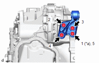
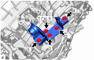
9. INSTALL NO. 2 ENGINE MOVING CONTROL ROD
|
(a) Install the No. 2 engine moving control rod to the continuously variable transaxle assembly with the 4 bolts in the order shown in the illustration. Torque: 44 N·m {449 kgf·cm, 32 ft·lbf} |
|
10. INSTALL FRONT SUSPENSION CROSSMEMBER SUB-ASSEMBLY
(a) Install the front suspension crossmember sub-assembly to the No. 2 engine moving control rod with the bolt.
Torque:
170 N·m {1734 kgf·cm, 125 ft·lbf}
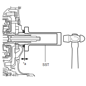
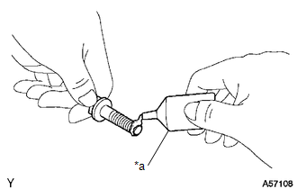
11. INSTALL CVT OIL PUMP TYPE T OIL SEAL
(a) Ensure that there is no dirt or foreign matter on your hands, and then apply MP grease to the entire periphery of the lip of a new CVT oil pump type T oil seal.
(b) Temporarily install the CVT oil pump type T oil seal by pressing it to the installation surface of the oil pump housing manually.
NOTICE:
Be sure to install the CVT oil pump type T oil seal in the correct direction.
(c) Clean the CVT oil pump type T oil seal contact surface of SST and the area around it.
SST: 09309-36010
|
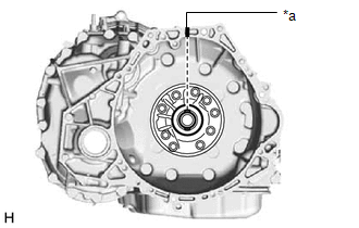
(d) Using SST, drive the CVT oil pump type T oil seal in evenly, until it is even with the side surface of the oil pump housing. Standard Depth: 0 to 0.5 mm (0 to 0.0196 in.) NOTICE:
HINT: The CVT oil pump type T oil seal should be driven in between 0 to 0.5 mm (0 to 0.0196 in.) as measured from the side surface of the oil pump housing. |
|
12. INSTALL TORQUE CONVERTER ASSEMBLY
|
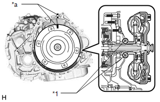
(a) Turn the front oil pump drive gear so that the wide groove is at the top and place a matchmark on the transaxle housing. NOTICE: Align the matchmark with the wide groove of the transaxle housing. |
|
|
(b) Place a matchmark on the torque converter assembly so that the position of its key is clearly indicated. |
|
|
(c) Align the matchmark on the transaxle housing with the one on the torque converter assembly and engage the splines of the input shaft with the turbine runner splines. NOTICE:
|
|
|
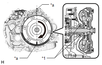
(d) Rotate the torque converter assembly approximately 180° and engage the splines of the stator shaft with the stator assembly. NOTICE:
|
|
|
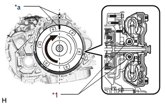
(e) Rotate the torque converter assembly approximately 180° again, align the matchmark on the torque converter assembly with the one on the transaxle housing and insert the key of the torque converter assembly into the groove of the oil pump drive gear. NOTICE:
|
|
(f) Clean the drive plate and torque converter assembly setting bolt holes.
|
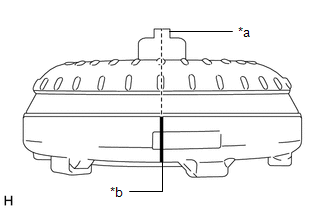
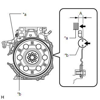
(g) Using a vernier caliper and straightedge, measure the dimension (A) between the continuously variable transaxle assembly contact surface of the engine assembly*a and the torque converter assembly contact surfaces of the drive plate*b. |
|
|
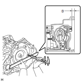
(h) Using a vernier caliper and straightedge, measure the dimension (B) shown in the illustration and check that the dimension (B) is more than the dimension (A), which was measured in the previous step. Standard: B = A + 1 mm (0.0394 in.) or more NOTICE:
|
|
13. INSTALL ENGINE ASSEMBLY
|
(a) Apply clutch spline grease to the surface of the crankshaft that contacts the torque converter assembly centerpiece. Clutch Spline Grease: Toyota Genuine Clutch Spline Grease or equivalent Maximum Grease Amount Approximately 1 g (0.0353 oz.) |
|
|
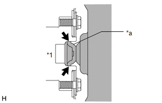
(b) Confirm that the 2 knock pins are installed to the engine assembly and are not damaged. |
|
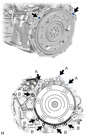
(c) Install the engine assembly to the continuously variable transaxle assembly with the 8 bolts.
Torque:
Bolt (A) :
38 N·m {387 kgf·cm, 28 ft·lbf}
Bolt (B) :
40 N·m {408 kgf·cm, 30 ft·lbf}
NOTICE:
- Make sure that the wire harness or similar items are not pinched between the contact surfaces.
- Do not use excess force when installing the continuously variable transaxle assembly.
- When mounting the continuously variable transaxle assembly to the engine assembly, make sure to securely fit the 2 knock pins into the knock holes.
- Check that the torque converter assembly rotates.
- When tightening the bolts, be sure that the mating surfaces of the engine assembly and the continuously variable transaxle assembly are in close contact with one another.
HINT:
- Bolt (A): Install from continuously variable transaxle assembly side
- Bolt (B): Install from engine assembly side
14. INSTALL TRANSVERSE ENGINE ENGINE MOUNTING BRACKET
|
(a) Install the transverse engine engine mounting bracket with the 5 new bolts. Torque: 41 N·m {418 kgf·cm, 30 ft·lbf} |
|
15. INSTALL FLYWHEEL HOUSING SIDE COVER
Click here
.gif)
16. INSTALL STARTER ASSEMBLY
Click here
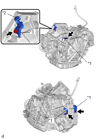
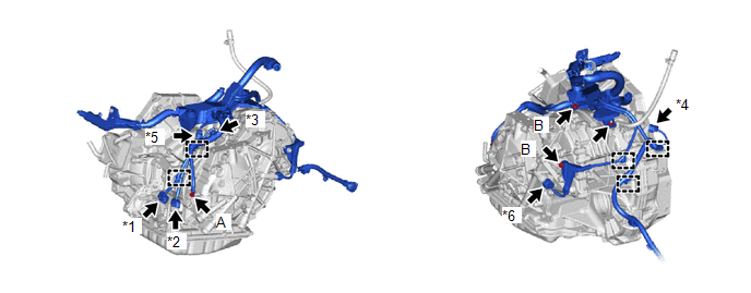
17. CONNECT ENGINE WIRE
(a) Engage the 5 clamps to disconnect the engine wire to the continuously variable transaxle assembly.
|
*1 |
Park/Neutral Position Switch Connector |
*2 |
Transmission Wire Connector |
|
*3 |
Transmission Revolution Sensor (NIN) Connector |
*4 |
Transmission Revolution Sensor (NOUT) Connector |
|
*5 |
Transmission Revolution Sensor (NT) Connector |
*6 |
Oil Pressure Sensor Connector |
(b) Connect the engine wire to the continuously variable transaxle assembly with the 3 bolts and nut.
Torque:
Bolt (A) :
8.5 N·m {87 kgf·cm, 75 in·lbf}
Bolt (B) :
8.0 N·m {82 kgf·cm, 71 in·lbf}
Nut :
8.0 N·m {82 kgf·cm, 71 in·lbf}
(c) Connect the oil pressure sensor connector.
(d) Connect the transmission revolution sensor (NOUT) connector.
(e) Connect the transmission revolution sensor (NIN) connector.
(f) Connect the transmission revolution sensor (NT) connector.
(g) Connect the transmission wire connector.
(h) Connect the park/neutral position switch connector.
|
(i) Engage the 3 clamps to connect the engine wire to the front suspension crossmember sub-assembly. |
|
.png)
18. CONNECT NO. 5 WATER BY-PASS HOSE
(a) Connect the No. 5 water by-pass hose to the transmission oil cooler, and slide the clip to secure it.
NOTICE:
- Align each paint mark on the No. 5 water by-pass hose with each one on the transmission oil cooler.
- Fully insert the No. 5 water by-pass hose to the 2nd rib on each oil cooler pipe.
19. CONNECT NO. 3 WATER BY-PASS HOSE
(a) Connect the No. 3 water by-pass hose to the transmission oil cooler, and slide the clip to secure it.
NOTICE:
- Align each paint mark on the No. 3 water by-pass hose with each one on the transmission oil cooler.
- Fully insert the No. 3 water by-pass hose to the 2nd rib on each oil cooler pipe.
20. INSTALL ENGINE ASSEMBLY WITH TRANSAXLE
Click here
21. INSTALL DRIVE PLATE AND TORQUE CONVERTER ASSEMBLY SETTING BOLT
(a) Clean the threads of the 6 drive plate and torque converter assembly setting bolts.
|
(b) Apply a few drops of adhesive to 2 or 3 threads at the tip of each of the 6 drive plate and torque converter assembly setting bolts. Adhesive: Toyota Genuine Adhesive 1324, Three Bond 1324 or equivalent NOTICE: In order to ensure proper installation of the 6 drive plate and torque converter assembly setting bolts, apply adhesive to the 6 drive plate and torque converter assembly setting bolts and install them within 10 minutes of adhesive application. |
|
(c) Turn the crankshaft to gain access to the installation locations of the 6 drive plate and torque converter assembly setting bolts and install each bolt while holding the crankshaft pulley with SST.
Torque:
41 N·m {418 kgf·cm, 30 ft·lbf}
NOTICE:
First install the black-colored bolt, and then the remaining 5 silver-colored bolts.
22. INSTALL FLYWHEEL HOUSING UNDER COVER
(a) Install the flywheel housing under cover.
23. RESET MEMORY
Click here
 Removal
REMOVAL
CAUTION / NOTICE / HINT
The necessary procedures (adjustment, calibration, initialization, or registration)
that must be performed after parts are removed, installed, or replaced during th ...

Other materials:
Toyota CH-R Service Manual > Tire Pressure Warning System: System Diagram
SYSTEM DIAGRAM
HINT:
Each tire pressure warning valve and transmitter sends its transmitter ID, temperature
and tire pressure information to the tire pressure warning ECU and receiver.
Transmitting ECU (Transmitter)
Receiving ECU
Signal
Communicat ...
Toyota CH-R Service Manual > Steering Lock System: Precaution
PRECAUTION
PRECAUTIONS WHEN CHECKING FOR DTCS
(a) When the cable is disconnected from the negative (-) battery terminal, the
DTCs stored in the steering lock ECU (steering lock actuator or upper bracket assembly)
are cleared. Be sure to record any output DTCs immediately.
(b) Normally, with t ...
Toyota C-HR (AX20) 2023-2026 Owner's Manual
Toyota CH-R Owners Manual
- For safety and security
- Instrument cluster
- Operation of each component
- Driving
- Interior features
- Maintenance and care
- When trouble arises
- Vehicle specifications
- For owners
Toyota CH-R Service Manual
- Introduction
- Maintenance
- Audio / Video
- Cellular Communication
- Navigation / Multi Info Display
- Park Assist / Monitoring
- Brake (front)
- Brake (rear)
- Brake Control / Dynamic Control Systems
- Brake System (other)
- Parking Brake
- Axle And Differential
- Drive Shaft / Propeller Shaft
- K114 Cvt
- 3zr-fae Battery / Charging
- Networking
- Power Distribution
- Power Assist Systems
- Steering Column
- Steering Gear / Linkage
- Alignment / Handling Diagnosis
- Front Suspension
- Rear Suspension
- Tire / Wheel
- Tire Pressure Monitoring
- Door / Hatch
- Exterior Panels / Trim
- Horn
- Lighting (ext)
- Mirror (ext)
- Window / Glass
- Wiper / Washer
- Door Lock
- Heating / Air Conditioning
- Interior Panels / Trim
- Lighting (int)
- Meter / Gauge / Display
- Mirror (int)
- Power Outlets (int)
- Pre-collision
- Seat
- Seat Belt
- Supplemental Restraint Systems
- Theft Deterrent / Keyless Entry

0.0076