Toyota CH-R Service Manual: Reassembly
REASSEMBLY
PROCEDURE
1. INSTALL FRONT DRIVE SHAFT DUST COVER LH
|
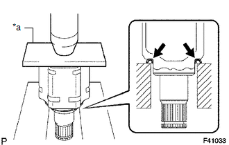
(a) Using a steel plate and a press, install a new front drive shaft dust cover LH. NOTICE:
|
|
2. INSTALL FRONT DRIVE SHAFT DUST COVER RH
|
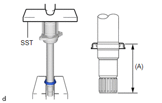
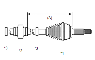
(a) Using SST and a press, install a new front drive shaft dust cover RH until the distance (A) from the tip of the center drive shaft to the front drive shaft dust cover RH meets the specification. SST: 09527-10011 Distance (A): 91.0 to 92.0 mm (3.59 to 3.62 in.) NOTICE:
|
|
3. INSTALL FRONT AXLE OUTBOARD JOINT BOOT
|
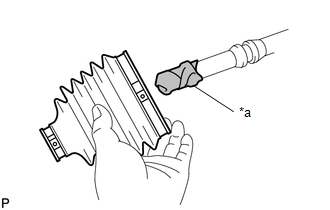
(a) Wrap the splines of the front drive outboard joint shaft assembly with protective tape to prevent the boot from being damaged. |
|
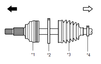
(b) Install new parts onto the front drive outboard joint shaft assembly in the following order:
|
*1 |
Front Drive Outboard Joint Shaft Assembly |
|
*2 |
Front No. 2 Axle Outboard Joint Boot Clamp |
|
*3 |
Front Axle Outboard Joint Boot |
|
*4 |
Front Axle Outboard Joint Boot Clamp |
.png) |
Outboard joint side |
.png) |
Inboard joint side |
(1) Front No. 2 axle outboard joint boot clamp
(2) Front axle outboard joint boot
(3) Front axle outboard joint boot clamp
(c) Pack the joint portion of the front drive outboard joint shaft assembly and front axle outboard joint boot with grease.
Standard grease capacity:
80 to 100 g (2.83 to 3.52 oz.)
(d) Install the front axle outboard joint boot into the front drive outboard joint shaft assembly groove.
NOTICE:
- Do not allow grease to adhere to the boot clamp track of the outboard joint boot.
- Keep the inside of the outboard joint boot free of foreign matter.
4. INSTALL FRONT NO. 2 AXLE OUTBOARD JOINT BOOT CLAMP
(a) Secure the drive shaft in a vise between aluminum plates.
NOTICE:
Do not overtighten the vise.
(b) Install the front No. 2 axle outboard joint boot clamp onto the front axle outboard joint boot.
|
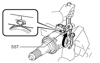
(c) Place SST onto the front No. 2 axle outboard joint boot clamp, press it against the boot and slightly tighten SST. SST: 09521-24010 |
|
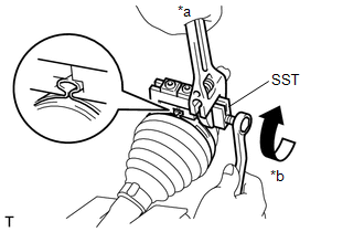
(d) Tighten SST so that the front No. 2 axle outboard joint boot clamp is pinched.
NOTICE:
Do not overtighten SST.
(e) Remove SST.
|
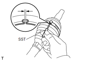
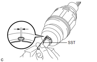
(f) Using SST, measure the clearance of the front No. 2 axle outboard joint boot clamp. SST: 09240-00020 Clearance: 1.2 to 4.0 mm (0.0473 to 0.157 in.) If the clearance is outside the specified range, retighten SST. |
|
5. INSTALL FRONT AXLE OUTBOARD JOINT BOOT CLAMP
(a) Install the front axle outboard joint boot clamp onto the front axle outboard joint boot.
|
(b) Place SST onto the front axle outboard joint boot clamp, press it against the boot and slightly tighten SST. SST: 09521-24010 |
|
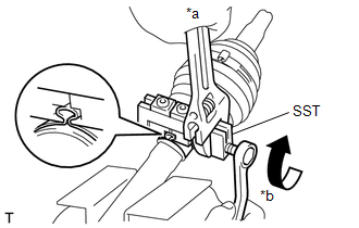
(c) Tighten SST so that the front axle outboard joint boot clamp is pinched.
NOTICE:
Do not overtighten SST.
(d) Remove SST.
|
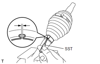
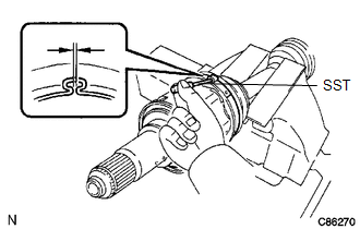
(e) Using SST, measure the clearance of the front axle outboard joint boot clamp. SST: 09240-00020 Clearance: 1.2 to 4.0 mm (0.0473 to 0.157 in.) If the clearance is outside the specified range, retighten SST. |
|
6. INSTALL FRONT DRIVE SHAFT DAMPER LH
|
(a) Install parts to the front drive outboard joint shaft assembly in the following order as shown in the illustration. (1) New front drive shaft damper clamp (2) Front drive shaft damper LH (3) New front drive shaft damper clamp |
|
(b) Set the dimension (A) as specified below.
Dimension (A):
229 to 233 mm (9.02 to 9.17 in.)
(c) Secure the drive shaft in a vise between aluminum plates.
NOTICE:
Do not overtighten the vise.
(d) Install the 2 front drive shaft damper clamps to the front drive shaft damper LH.
NOTICE:
Be sure to install the clamp in the correct position.
|
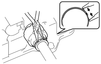
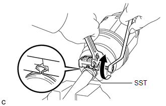
(e) Using needle-nose pliers, engage the 2 claws to install the 2 front drive shaft damper clamps as shown in the illustration. |
|
7. INSTALL FRONT DRIVE INBOARD JOINT ASSEMBLY
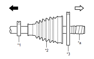
(a) Install new parts onto the front drive outboard joint shaft assembly in the following order:
|
*1 |
Front Axle Inboard Joint Boot Clamp |
|
*2 |
Front Axle Inboard Joint Boot |
|
*3 |
Front No. 2 Axle Inboard Joint Boot Clamp |
|
*a |
Protective Tape |
|
|
Outboard joint side |
|
|
Inboard joint side |
(1) Front axle inboard joint boot clamp
(2) Front axle inboard joint boot
(3) Front No. 2 axle inboard joint boot clamp
(b) Secure the drive shaft in a vise between aluminum plates.
NOTICE:
Do not overtighten the vise.
(c) Remove the protective tape.
|
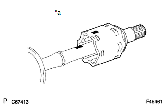
(d) Align the matchmarks and install the tripod joint to the front drive outboard joint shaft assembly. NOTICE: Face the serrated side of the tripod joint outward and install it to the outboard joint end. |
|
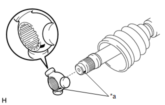
(e) Using a brass bar and a hammer, install the tripod joint to the front drive outboard joint shaft assembly.
NOTICE:
- Do not tap the areas where the rollers contact the tripod joint.
- Keep the tripod joint free of foreign matter.
- Make sure to install the tripod joint in the correct direction.
|
(f) Using a snap ring expander, install a new shaft snap ring to the front drive outboard joint shaft assembly. |
|
.png)
(g) Pack the front drive inboard joint assembly and front axle inboard boot with grease.
Standard grease capacity:
195 to 215 g (6.88 to 7.58 oz.)
|
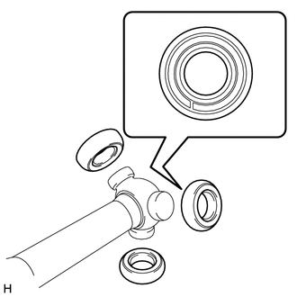
(h) Install the 3 rollers to the tripod joint. NOTICE:
|
|
|
(i) Align the matchmarks and install the front drive inboard joint assembly to the front drive outboard joint shaft assembly. |
|
8. INSTALL FRONT AXLE INBOARD JOINT BOOT
(a) Install the front axle inboard joint boot to the front drive inboard joint assembly.
|
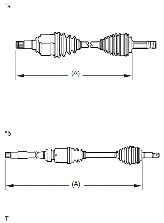
(b) Check whether each drive shaft dimension (A) is within specification. Dimension (A):
|
|
9. INSTALL FRONT AXLE INBOARD JOINT BOOT CLAMP
(a) Secure the drive shaft in a vise between aluminum plates.
NOTICE:
Do not overtighten the vise.
(b) Install the front axle inboard joint boot clamp onto the front axle inboard joint boot.
|
(c) Place SST onto the front axle inboard joint boot clamp, press it against the boot and slightly tighten SST. SST: 09521-24010 |
|
(d) Tighten SST so that the front axle inboard joint boot clamp is pinched.
NOTICE:
Do not overtighten SST.
(e) Remove SST.
|
(f) Using SST, measure the clearance of the front axle inboard joint boot clamp. SST: 09240-00020 Clearance: 1.2 to 4.0 mm (0.0473 to 0.157 in.) If the clearance is outside the specified range, retighten SST. |
|
10. INSTALL FRONT NO. 2 AXLE INBOARD JOINT BOOT CLAMP
(a) Install the front No. 2 axle inboard joint boot clamp onto the front axle inboard joint boot.
|
(b) Place SST onto the front No. 2 axle inboard joint boot clamp, press it against the boot and slightly tighten SST. SST: 09521-24010 |
|
(c) Tighten SST so that the front No. 2 axle inboard joint boot clamp is pinched.
NOTICE:
Do not overtighten SST.
(d) Remove SST.
|
(e) Using SST, measure the clearance of the front No. 2 axle inboard joint boot clamp. SST: 09240-00020 Clearance: 1.2 to 4.0 mm (0.0473 to 0.157 in.) If the clearance is outside the specified range, retighten SST. |
|
11. INSPECT FRONT DRIVE SHAFT ASSEMBLY
Click here
.gif)
 Inspection
INSPECTION
PROCEDURE
1. INSPECT FRONT DRIVE SHAFT ASSEMBLY
(a) Check that there is no excessive play in the radial direction of
the outboard joint.
...
 Installation
INSTALLATION
CAUTION / NOTICE / HINT
HINT:
Use the same procedure for the RH side and LH side.
The following procedure is for the LH side.
PROCEDURE
1. INSTALL FRONT DRIVE INBOA ...
Other materials:
Toyota CH-R Owners Manual > Dynamic radar cruise control with full-speed range: Setting the vehicle speed (vehicle-to-vehicle distance control mode)
1. Press the "ON-OFF" button to activate the cruise control.
Radar cruise control indicator will come on and a message will be displayed on
the multi-information display.
Press the button again to deactivate the cruise control.
If the "ON-OFF" button is pressed and held for ...
Toyota CH-R Service Manual > Front Door Courtesy Switch: Removal
REMOVAL
CAUTION / NOTICE / HINT
HINT:
Use the same procedure for the LH and RH sides.
The procedure described below is for the LH side.
PROCEDURE
1. REMOVE BENCH TYPE REAR SEAT CUSHION ASSEMBLY
Click here
2. REMOVE REAR SEAT CUSHION LOCK HOOK
Click here
3. REMOVE FRONT ...
Toyota C-HR (AX20) 2023-2026 Owner's Manual
Toyota CH-R Owners Manual
- For safety and security
- Instrument cluster
- Operation of each component
- Driving
- Interior features
- Maintenance and care
- When trouble arises
- Vehicle specifications
- For owners
Toyota CH-R Service Manual
- Introduction
- Maintenance
- Audio / Video
- Cellular Communication
- Navigation / Multi Info Display
- Park Assist / Monitoring
- Brake (front)
- Brake (rear)
- Brake Control / Dynamic Control Systems
- Brake System (other)
- Parking Brake
- Axle And Differential
- Drive Shaft / Propeller Shaft
- K114 Cvt
- 3zr-fae Battery / Charging
- Networking
- Power Distribution
- Power Assist Systems
- Steering Column
- Steering Gear / Linkage
- Alignment / Handling Diagnosis
- Front Suspension
- Rear Suspension
- Tire / Wheel
- Tire Pressure Monitoring
- Door / Hatch
- Exterior Panels / Trim
- Horn
- Lighting (ext)
- Mirror (ext)
- Window / Glass
- Wiper / Washer
- Door Lock
- Heating / Air Conditioning
- Interior Panels / Trim
- Lighting (int)
- Meter / Gauge / Display
- Mirror (int)
- Power Outlets (int)
- Pre-collision
- Seat
- Seat Belt
- Supplemental Restraint Systems
- Theft Deterrent / Keyless Entry

0.0092