
Toyota CH-R Service Manual: Front Passenger Side Seat Belt Warning Light Malfunction
DESCRIPTION
When the ignition switch is ON, the combination meter assembly monitors the state of the front passenger side seat and the front seat inner belt assembly (front passenger seat) and also whether the front passenger seat is occupied. If the front passenger side seat belt is not fastened, the seat belt warning light of the combination meter assembly blinks. If the seat belt is fastened, the warning light goes off.
WIRING DIAGRAM
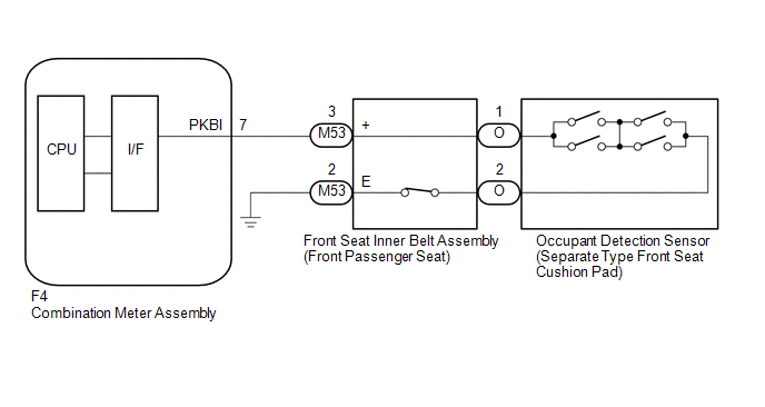
CAUTION / NOTICE / HINT
NOTICE:
When replacing the combination meter assembly, always replace it with a new one. If a combination meter assembly which was installed to another vehicle is used, the information stored in it will not match the information from the vehicle and a DTC may be stored.
HINT:
- The seat belt warning light on the combination meter assembly is used
for both the driver seat and front passenger seat. Check that the operation
of the seat belt warning light is normal first.
Click here
.gif)
- If the seat belt warning light does not operate for both the driver
seat and front passenger seat, replace the combination meter assembly.
Click here
PROCEDURE
|
1. |
READ VALUE USING TECHSTREAM (P-SEATBELT BUCKLE SW) |
(a) Connect the Techstream to the DLC3.
(b) Turn the ignition switch to ON.
(c) Turn the Techstream on.
(d) Enter the following menus: Body Electrical / Combination Meter / Data List.
(e) Read the Data List according to the display on the Techstream.
Body Electrical > Combination Meter > Data List|
Tester Display |
Measurement Item |
Range |
Normal Condition |
Diagnostic Note |
|---|---|---|---|---|
|
P-Seatbelt Buckle SW |
Front passenger seat belt buckle switch signal |
ON or OFF |
ON: Front passenger seat belt not fastened OFF: Front passenger seat belt fastened |
Perform the inspection while sitting in the front passenger side seat. |
|
Tester Display |
|---|
|
P-Seatbelt Buckle SW |
|
Result |
Proceed to |
|---|---|
|
ON or OFF is displayed on the Techstream screen according to the front passenger side seat belt condition and front passenger seat condition (occupied or unoccupied) |
A |
|
ON or OFF is not displayed normally on the Techstream screen according to the front passenger side seat belt condition |
B |
| A | .gif) |
REPLACE COMBINATION METER ASSEMBLY |
|
.gif)
|
2. |
CHECK HARNESS AND CONNECTOR (FRONT SEAT INNER BELT ASSEMBLY (FRONT PASSENGER SEAT) - COMBINATION METER ASSEMBLY AND BODY GROUND) |
(a) Disconnect the F4 combination meter assembly connector.
(b) Disconnect the M53 front seat inner belt assembly (front passenger seat) connector.
(c) Measure the resistance according to the value(s) in the table below.
Standard Resistance:
|
Tester Connection |
Condition |
Specified Condition |
|---|---|---|
|
F4-7 (PKBI) - M53-3 (+) |
Always |
Below 1 Ω |
|
F4-7 (PKBI) or M53-3 (+) - Body ground |
Always |
10 kΩ or higher |
|
M53-2 (E) - Body ground |
Always |
Below 1 Ω |
| NG | |
REPAIR OR REPLACE HARNESS OR CONNECTOR |
|
|
3. |
INSPECT FRONT SEAT INNER BELT ASSEMBLY (FRONT PASSENGER SEAT) |
(a) Remove the front seat inner belt assembly (front passenger seat).
Click here
(b) Inspect the front seat inner belt assembly (front passenger seat).
Click here
| NG | |
REPLACE FRONT SEAT INNER BELT ASSEMBLY (FRONT PASSENGER SEAT) |
|
|
4. |
INSPECT SEPARATE TYPE FRONT SEAT CUSHION PAD (OCCUPANT DETECTION SENSOR) |
(a) Remove the separate type front seat cushion pad (occupant detection sensor).
Click here
(b) Inspect the separate type front seat cushion pad (occupant detection sensor).
Click here
| OK | |
REPLACE COMBINATION METER ASSEMBLY |
| NG | |
REPLACE SEPARATE TYPE FRONT SEAT CUSHION PAD (OCCUPANT DETECTION SENSOR) |
 On-vehicle Inspection
ON-VEHICLE INSPECTION
PROCEDURE
1. INSPECT DRIVER SEAT BELT WARNING SYSTEM
HINT:
The seat belt warning light on the combination meter assembly is used for both
the driver seat and front passenge ...
 Tongue Plate Stopper
Components
COMPONENTS
ILLUSTRATION
*1
TONGUE PLATE STOPPER
-
-
●
Non-reusable part
-
-
...
Other materials:
Toyota CH-R Service Manual > Front Door: Components
COMPONENTS
ILLUSTRATION
*A
w/ Illumination
*B
for Driver Side
*C
for Front Passenger Side
-
-
*1
FRONT DOOR BELT SEAL
*2
FRONT DOOR GLASS INNER WEATHERS ...
Toyota CH-R Service Manual > Immobiliser System(w/ Smart Key System): Precaution
PRECAUTION
PRECAUTIONS WHEN USING TECHSTREAM
(a) When using the Techstream with the engine switch off, connect the Techstream
to the DLC3 and turn a courtesy light switch on and off at intervals of 1.5 seconds
or less until communication between the Techstream and the vehicle begins. Then
se ...
Toyota C-HR (AX20) 2023-2026 Owner's Manual
Toyota CH-R Owners Manual
- For safety and security
- Instrument cluster
- Operation of each component
- Driving
- Interior features
- Maintenance and care
- When trouble arises
- Vehicle specifications
- For owners
Toyota CH-R Service Manual
- Introduction
- Maintenance
- Audio / Video
- Cellular Communication
- Navigation / Multi Info Display
- Park Assist / Monitoring
- Brake (front)
- Brake (rear)
- Brake Control / Dynamic Control Systems
- Brake System (other)
- Parking Brake
- Axle And Differential
- Drive Shaft / Propeller Shaft
- K114 Cvt
- 3zr-fae Battery / Charging
- Networking
- Power Distribution
- Power Assist Systems
- Steering Column
- Steering Gear / Linkage
- Alignment / Handling Diagnosis
- Front Suspension
- Rear Suspension
- Tire / Wheel
- Tire Pressure Monitoring
- Door / Hatch
- Exterior Panels / Trim
- Horn
- Lighting (ext)
- Mirror (ext)
- Window / Glass
- Wiper / Washer
- Door Lock
- Heating / Air Conditioning
- Interior Panels / Trim
- Lighting (int)
- Meter / Gauge / Display
- Mirror (int)
- Power Outlets (int)
- Pre-collision
- Seat
- Seat Belt
- Supplemental Restraint Systems
- Theft Deterrent / Keyless Entry

0.0096