Toyota CH-R Service Manual: Installation
INSTALLATION
CAUTION / NOTICE / HINT
HINT:
- Use the same procedure for the RH side and LH side.
- The following procedure is for the LH side.
PROCEDURE
1. INSTALL FRONT DRIVE INBOARD JOINT HOLE SNAP RING LH (for LH Side)
(a) Install a new front drive inboard joint hole snap ring LH.
2. INSTALL FRONT DRIVE SHAFT ASSEMBLY LH
(a) Coat the splines of the front drive inboard joint assembly with Toyota Genuine CVT Fluid FE.
(b) Coat the lip of the front drive shaft oil seal LH with MP grease.
|
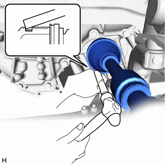
(c) Align the inboard joint splines, and using a brass bar and a hammer, install the front drive shaft assembly LH. NOTICE:
HINT: Confirm whether the drive shaft is securely driven in by checking the reaction force and sound. |
|
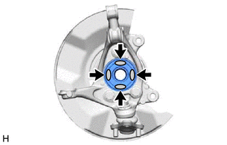
(d) Apply 0.1 to 0.3 g (0.00353 to 0.0105 oz.) of Toyota Body Grease W to each of the 4 areas shown in the illustration.
.png) |
Toyota Body Grease W |
|
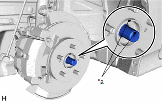
(e) Align the matchmarks and install the front drive shaft assembly LH to the front axle hub sub-assembly. NOTICE:
|
|
3. INSTALL FRONT DRIVE SHAFT ASSEMBLY RH
(a) Coat the splines of the front drive inboard joint assembly with Toyota Genuine CVT Fluid FE.
(b) Coat the lip of the front drive shaft oil seal RH with MP grease.
(c) Align the shaft splines and securely install the front drive shaft assembly RH.
NOTICE:
- Be careful not to damage the front drive shaft oil seal RH, inboard joint boot and drive shaft dust cover.
- When inserting the front drive shaft assembly RH, keep it level.
|
(d) Install the front drive shaft assembly RH with the 2 bolts. Torque: 63.7 N·m {650 kgf·cm, 47 ft·lbf} |
|
.png)
(e) Perform the same procedure as for the LH side.
4. CONNECT FRONT LOWER NO. 1 SUSPENSION ARM SUB-ASSEMBLY
Click here
.gif)
5. INSTALL FRONT STABILIZER LINK ASSEMBLY
Click here
6. CONNECT TIE ROD END SUB-ASSEMBLY
Click here
7. INSTALL FRONT SPEED SENSOR
Click here
8. INSTALL FRONT AXLE SHAFT NUT
(a) Clean the threaded parts on the front drive shaft assembly and a new front axle shaft nut using non-residue solvent.
NOTICE:
- Be sure to perform this work even when using a new front drive shaft assembly.
- Keep the threaded parts free of oil and foreign matter.
|
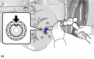
(b) Using a 30 mm deep socket wrench, install the front axle shaft nut. Torque: 216 N·m {2203 kgf·cm, 159 ft·lbf} HINT: Keep depressing the brake pedal to prevent the drive shaft from rotating. |
|
(c) Using a chisel and a hammer, stake the front axle shaft nut.
9. ADD CONTINUOUSLY VARIABLE TRANSAXLE FLUID
Click here
10. INSPECT FOR CONTINUOUSLY VARIABLE TRANSAXLE FLUID LEAK
11. INSTALL FRONT WHEELS
Click here
12. ADJUST FRONT WHEEL ALIGNMENT
Click here
13. INSTALL REAR ENGINE UNDER COVER LH
Click here
14. INSTALL REAR ENGINE UNDER COVER RH
Click here
15. INSTALL NO. 1 ENGINE UNDER COVER
Click here
16. CHECK FOR SPEED SENSOR SIGNAL
Click here
 Reassembly
REASSEMBLY
PROCEDURE
1. INSTALL FRONT DRIVE SHAFT DUST COVER LH
(a) Using a steel plate and a press, install a new front drive shaft
dust cover LH.
NOTICE:
The dus ...
 K114 Cvt
...
Other materials:
Toyota CH-R Service Manual > Audio And Visual System(for Radio And Display Type): Parts Location
PARTS LOCATION
ILLUSTRATION
*1
MAP LIGHT ASSEMBLY (TELEPHONE MICROPHONE ASSEMBLY)
*2
SKID CONTROL ECU (BRAKE ACTUATOR ASSEMBLY)
ILLUSTRATION
*1
FRONT NO. 1 SPEAKER ASSEMBLY LH
*2
FRONT NO. 1 SPEA ...
Toyota CH-R Service Manual > Front Differential Oil Seal: Components
COMPONENTS
ILLUSTRATION
*1
NO. 1 ENGINE UNDER COVER
*2
REAR ENGINE UNDER COVER LH
*3
REAR ENGINE UNDER COVER RH
-
-
N*m (kgf*cm, ft.*lbf): Specified torque
-
...
Toyota C-HR (AX20) 2023-2026 Owner's Manual
Toyota CH-R Owners Manual
- For safety and security
- Instrument cluster
- Operation of each component
- Driving
- Interior features
- Maintenance and care
- When trouble arises
- Vehicle specifications
- For owners
Toyota CH-R Service Manual
- Introduction
- Maintenance
- Audio / Video
- Cellular Communication
- Navigation / Multi Info Display
- Park Assist / Monitoring
- Brake (front)
- Brake (rear)
- Brake Control / Dynamic Control Systems
- Brake System (other)
- Parking Brake
- Axle And Differential
- Drive Shaft / Propeller Shaft
- K114 Cvt
- 3zr-fae Battery / Charging
- Networking
- Power Distribution
- Power Assist Systems
- Steering Column
- Steering Gear / Linkage
- Alignment / Handling Diagnosis
- Front Suspension
- Rear Suspension
- Tire / Wheel
- Tire Pressure Monitoring
- Door / Hatch
- Exterior Panels / Trim
- Horn
- Lighting (ext)
- Mirror (ext)
- Window / Glass
- Wiper / Washer
- Door Lock
- Heating / Air Conditioning
- Interior Panels / Trim
- Lighting (int)
- Meter / Gauge / Display
- Mirror (int)
- Power Outlets (int)
- Pre-collision
- Seat
- Seat Belt
- Supplemental Restraint Systems
- Theft Deterrent / Keyless Entry

0.0086