Toyota CH-R Service Manual: Disassembly
DISASSEMBLY
PROCEDURE
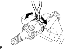
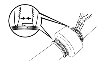
1. SEPARATE FRONT NO. 2 AXLE INBOARD JOINT BOOT CLAMP
(a) Secure the drive shaft in a vise between aluminum plates.
NOTICE:
Do not overtighten the vise.
|
(b) Using pliers, separate the front No. 2 axle inboard joint boot clamp. |
|
2. SEPARATE FRONT AXLE INBOARD JOINT BOOT CLAMP
(a) Separate the front axle inboard joint boot clamp.
HINT:
Perform the same procedure as for the front No. 2 axle inboard joint boot clamp.
3. SEPARATE FRONT AXLE INBOARD JOINT BOOT
(a) Separate the front axle inboard joint boot from the front drive inboard joint assembly.
4. REMOVE FRONT DRIVE INBOARD JOINT ASSEMBLY
(a) Remove the old grease from the front drive inboard joint assembly.
|
(b) Put matchmarks on the front drive inboard joint assembly and front drive outboard joint shaft assembly. NOTICE: Do not use a punch for the marks. |
|
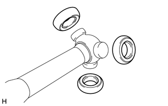
(c) Remove the front drive inboard joint assembly from the front drive outboard joint shaft assembly.
NOTICE:
- Be careful when removing the front drive inboard joint assembly from the front drive outboard joint shaft assembly as the rollers of the tripod joint may fall out.
- Do not drop the rollers of the tripod joint.
|
(d) Remove the 3 rollers from the tripod joint. |
|
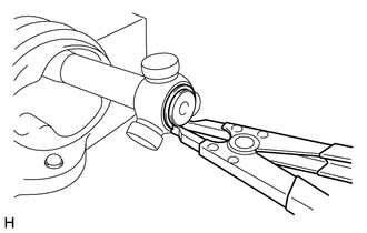
(e) Secure the drive shaft in a vise between aluminum plates.
NOTICE:
Do not overtighten the vise.
|
(f) Using a snap ring expander, remove the front drive inner shaft inner shaft snap ring from the front drive outboard joint shaft assembly. |
|
|
(g) Put matchmarks on the front drive outboard joint shaft assembly and tripod joint. NOTICE: Do not use a punch for the marks. |
|

(h) Using a brass bar and a hammer, tap out the tripod joint from the front drive outboard joint shaft assembly.
NOTICE:
- Do not tap the areas where the rollers contact the tripod joint.
- Do not drop the tripod joint.
5. REMOVE FRONT AXLE INBOARD JOINT BOOT
(a) Remove the front No. 2 axle inboard joint boot clamp, front axle inboard joint boot and front axle inboard joint boot clamp.
6. REMOVE FRONT DRIVE SHAFT DAMPER LH
|
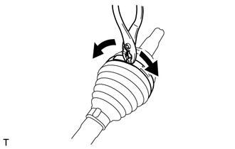
(a) Using needle-nose pliers, separate the 2 front drive shaft damper clamps. |
|
(b) Remove the front drive shaft damper and 2 front drive shaft damper clamps from the front drive outboard joint shaft assembly.
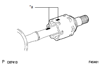
7. SEPARATE FRONT NO. 2 AXLE OUTBOARD JOINT BOOT CLAMP
|
(a) Using pliers, separate the front No. 2 axle outboard joint boot clamp as shown in the illustration. |
|
8. SEPARATE FRONT AXLE OUTBOARD JOINT BOOT CLAMP
(a) Separate the front axle outboard joint boot clamp.
HINT:
Perform the same procedure as for the front No. 2 axle outboard joint boot clamp.
9. REMOVE FRONT AXLE OUTBOARD JOINT BOOT
(a) Remove the front axle outboard joint boot clamp, front axle outboard joint boot and front No. 2 axle outboard joint boot clamp from the front drive outboard joint shaft assembly.
(b) Remove the old grease from the outboard joint.
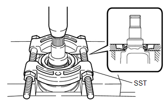
10. REMOVE FRONT DRIVE SHAFT DUST COVER LH
HINT:
Only perform the following procedure if the front drive shaft dust cover LH is deformed.
|
(a) Using SST and a press, remove the front drive shaft dust cover LH. SST: 09950-00020 NOTICE:
|
|
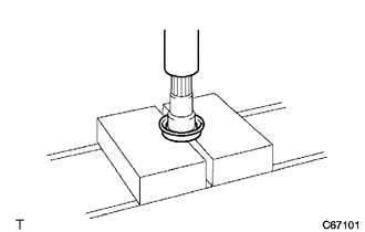
11. REMOVE FRONT DRIVE SHAFT DUST COVER RH
|
(a) Using a press, remove the front drive shaft dust cover RH. NOTICE: Be careful not to drop the front drive inboard joint assembly. |
|
 Removal
REMOVAL
CAUTION / NOTICE / HINT
The necessary procedures (adjustment, calibration, initialization, or registration)
that must be performed after parts are removed and installed, or replaced during ...
 Inspection
INSPECTION
PROCEDURE
1. INSPECT FRONT DRIVE SHAFT ASSEMBLY
(a) Check that there is no excessive play in the radial direction of
the outboard joint.
...
Other materials:
Toyota CH-R Service Manual > Tire Pressure Warning System: ECU Power Source Circuit
DESCRIPTION
This is the power source for the tire pressure warning ECU and receiver.
WIRING DIAGRAM
CAUTION / NOTICE / HINT
NOTICE:
When replacing the tire pressure warning ECU and receiver, read the
transmitter IDs stored in the old ECU using the Techstream and write them
dow ...
Toyota CH-R Service Manual > Lighting (ext): Automatic High Beam Main Switch
Components
COMPONENTS
ILLUSTRATION
*1
AUTO HIGH BEAM SWITCH
*2
INSTRUMENT CLUSTER FINISH PANEL SUB-ASSEMBLY
Removal
REMOVAL
PROCEDURE
1. REMOVE INSTRUMENT CLUSTER FINISH PANEL SUB-ASSEMBLY
Click here
2. REMOVE AUTO HIGH BEAM ...
Toyota C-HR (AX20) 2023-2026 Owner's Manual
Toyota CH-R Owners Manual
- For safety and security
- Instrument cluster
- Operation of each component
- Driving
- Interior features
- Maintenance and care
- When trouble arises
- Vehicle specifications
- For owners
Toyota CH-R Service Manual
- Introduction
- Maintenance
- Audio / Video
- Cellular Communication
- Navigation / Multi Info Display
- Park Assist / Monitoring
- Brake (front)
- Brake (rear)
- Brake Control / Dynamic Control Systems
- Brake System (other)
- Parking Brake
- Axle And Differential
- Drive Shaft / Propeller Shaft
- K114 Cvt
- 3zr-fae Battery / Charging
- Networking
- Power Distribution
- Power Assist Systems
- Steering Column
- Steering Gear / Linkage
- Alignment / Handling Diagnosis
- Front Suspension
- Rear Suspension
- Tire / Wheel
- Tire Pressure Monitoring
- Door / Hatch
- Exterior Panels / Trim
- Horn
- Lighting (ext)
- Mirror (ext)
- Window / Glass
- Wiper / Washer
- Door Lock
- Heating / Air Conditioning
- Interior Panels / Trim
- Lighting (int)
- Meter / Gauge / Display
- Mirror (int)
- Power Outlets (int)
- Pre-collision
- Seat
- Seat Belt
- Supplemental Restraint Systems
- Theft Deterrent / Keyless Entry

0.014