Toyota CH-R Service Manual: ECU Power Source Circuit
DESCRIPTION
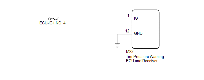
This is the power source for the tire pressure warning ECU and receiver.
WIRING DIAGRAM
CAUTION / NOTICE / HINT
NOTICE:
- When replacing the tire pressure warning ECU and receiver, read the
transmitter IDs stored in the old ECU using the Techstream and write them
down before removal.
Click here
.gif)
- It is necessary to perform initialization
after registration
of the transmitter IDs into the tire pressure warning ECU and receiver if
the ECU has been replaced.
HINT:
Inspect the fuses for circuits related to this system before performing the following inspection procedure.
PROCEDURE
|
1. |
CHECK HARNESS AND CONNECTOR (ECU - BATTERY AND BODY GROUND) |
|
(a) Disconnect the M23 tire pressure warning ECU and receiver connector. |
|
.png)
(b) Measure the voltage according to the value(s) in the table below.
Standard Voltage:
|
Tester Connection |
Condition |
Specified Condition |
|---|---|---|
|
M23-1 (IG) - Body ground |
Ignition switch to ON |
10 to 16 V |
|
Ignition switch off |
Below 1 V |
(c) Measure the resistance according to the value(s) in the table below.
Standard Resistance:
|
Tester Connection |
Condition |
Specified Condition |
|---|---|---|
|
M23-12 (GND) - Body ground |
Always |
Below 1 Ω |
| OK | .gif) |
REPLACE TIRE PRESSURE WARNING ECU AND RECEIVER |
| NG | |
REPAIR OR REPLACE HARNESS OR CONNECTOR |
 Transmitter ID1 Operation Stop (C2111/11-C2115/15)
DESCRIPTION
The tire pressure warning valve and transmitters that are installed in the tire
and wheel assemblies measure the tire pressures. The measured values are transmitted
to the tire pressu ...
 Tire Pressure Warning Light Circuit
DESCRIPTION
If the tire pressure warning ECU and receiver detects any problems, the tire
pressure warning light blinks (stays on after blinking for 1 minute) and tire pressure
monitoring is cance ...
Other materials:
Toyota CH-R Service Manual > Audio And Visual System(for Radio And Display Type): Voice is not Recognized
PROCEDURE
1.
CHECK CONDITION
(a) While paying attention to the condition of the spoken voice command, perform
a voice recognition operation.
OK:
Voice command is recognized normally.
HINT:
When the voice command is recognized, the content of the voice ...
Toyota CH-R Service Manual > Navigation System: Vehicle Speed Signal Circuit between Radio Receiver and Combination Meter
DESCRIPTION
for Automatic Sound Levelizer (ASL):
This circuit is necessary for the Automatic Sound Levelizer (ASL) built
into the radio and display receiver assembly.
The Automatic Sound Levelizer (ASL) function automatically adjusts the
audio system volume level in order to com ...
Toyota C-HR (AX20) 2023-2026 Owner's Manual
Toyota CH-R Owners Manual
- For safety and security
- Instrument cluster
- Operation of each component
- Driving
- Interior features
- Maintenance and care
- When trouble arises
- Vehicle specifications
- For owners
Toyota CH-R Service Manual
- Introduction
- Maintenance
- Audio / Video
- Cellular Communication
- Navigation / Multi Info Display
- Park Assist / Monitoring
- Brake (front)
- Brake (rear)
- Brake Control / Dynamic Control Systems
- Brake System (other)
- Parking Brake
- Axle And Differential
- Drive Shaft / Propeller Shaft
- K114 Cvt
- 3zr-fae Battery / Charging
- Networking
- Power Distribution
- Power Assist Systems
- Steering Column
- Steering Gear / Linkage
- Alignment / Handling Diagnosis
- Front Suspension
- Rear Suspension
- Tire / Wheel
- Tire Pressure Monitoring
- Door / Hatch
- Exterior Panels / Trim
- Horn
- Lighting (ext)
- Mirror (ext)
- Window / Glass
- Wiper / Washer
- Door Lock
- Heating / Air Conditioning
- Interior Panels / Trim
- Lighting (int)
- Meter / Gauge / Display
- Mirror (int)
- Power Outlets (int)
- Pre-collision
- Seat
- Seat Belt
- Supplemental Restraint Systems
- Theft Deterrent / Keyless Entry

0.0087