Toyota CH-R Service Manual: Removal
REMOVAL
CAUTION / NOTICE / HINT
The necessary procedures (adjustment, calibration, initialization, or registration) that must be performed after parts are removed and installed, or replaced during front drive shaft assembly removal/installation are shown below.
Necessary Procedures After Parts Removed/Installed/Replaced|
Replaced Part or Performed Procedure |
Necessary Procedure |
Effect/Inoperative Function when Necessary Procedure not Performed |
Link |
|---|---|---|---|
|
Front wheel alignment adjustment |
|
|
|
HINT:
- Use the same procedure for the RH side and LH side.
- The following procedure is for the LH side.
PROCEDURE
1. REMOVE FRONT WHEELS
Click here
.gif)
2. REMOVE NO. 1 ENGINE UNDER COVER
Click here
3. REMOVE REAR ENGINE UNDER COVER LH
Click here
4. REMOVE REAR ENGINE UNDER COVER RH
Click here
5. DRAIN CONTINUOUSLY VARIABLE TRANSAXLE FLUID
Click here
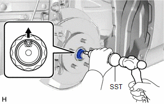
6. REMOVE FRONT AXLE SHAFT NUT
|
(a) Using SST and a hammer, release the staked part of the front axle shaft nut. SST: 09930-00010 NOTICE: Loosen the staked part of the front axle shaft nut completely, otherwise the threads of the drive shaft may be damaged. |
|
(b) While applying the brakes, remove the front axle shaft nut.
7. SEPARATE FRONT SPEED SENSOR
Click here
8. SEPARATE TIE ROD END SUB-ASSEMBLY
Click here
9. SEPARATE FRONT STABILIZER LINK ASSEMBLY
Click here
10. SEPARATE FRONT LOWER NO. 1 SUSPENSION ARM SUB-ASSEMBLY
Click here
11. SEPARATE FRONT DRIVE SHAFT ASSEMBLY
Click here
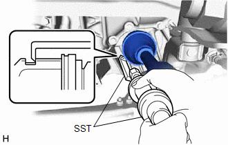
12. REMOVE FRONT DRIVE SHAFT ASSEMBLY LH
|
(a) Using SST, remove the front drive shaft assembly LH. SST: 09520-01010 SST: 09520-24010 09520-32040 NOTICE:
|
|
13. REMOVE FRONT DRIVE SHAFT ASSEMBLY RH
|
(a) Remove the 2 bolts from the front drive shaft assembly RH. |
|
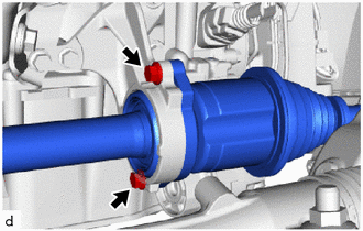
(b) Remove the front drive shaft assembly RH from the drive shaft bearing bracket.
NOTICE:
- Be careful not to damage the transaxle oil seal, inboard joint boot and drive shaft dust cover.
- Be careful not to drop the front drive shaft assembly RH.
HINT:
If the spline connection is stiff, using a brass bar and hammer, lightly tap the inboard joint assembly to remove it.
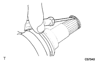
14. REMOVE FRONT DRIVE INBOARD JOINT HOLE SNAP RING LH (for LH Side)
|
(a) Using a screwdriver, remove the front drive inboard joint hole snap ring LH. |
|
 Components
COMPONENTS
ILLUSTRATION
*1
NO. 1 ENGINE UNDER COVER
*2
REAR ENGINE UNDER COVER LH
*3
REAR ENGINE UNDER COVER RH
- ...
 Disassembly
DISASSEMBLY
PROCEDURE
1. SEPARATE FRONT NO. 2 AXLE INBOARD JOINT BOOT CLAMP
(a) Secure the drive shaft in a vise between aluminum plates.
NOTICE:
Do not overtighten the vise.
(b) Usin ...
Other materials:
Toyota CH-R Service Manual > Airbag System: Short in Rear Pretensioner Squib LH Circuit (B1925/78-B1928/78)
DESCRIPTION
The rear pretensioner squib LH circuit consists of the airbag sensor assembly
and rear seat 3 point type outer belt assembly LH.
The airbag sensor assembly uses this circuit to deploy the pretensioner when
deployment conditions are met.
These DTCs are stored when a malfunction is ...
Toyota CH-R Service Manual > Front Stabilizer Bar: Removal
REMOVAL
CAUTION / NOTICE / HINT
The necessary procedures (adjustment, calibration, initialization, or registration)
that must be performed after parts are removed and installed, or replaced during
front stabilizer bar removal/installation are shown below.
Necessary Procedures After Parts Remo ...
Toyota C-HR (AX20) 2023-2026 Owner's Manual
Toyota CH-R Owners Manual
- For safety and security
- Instrument cluster
- Operation of each component
- Driving
- Interior features
- Maintenance and care
- When trouble arises
- Vehicle specifications
- For owners
Toyota CH-R Service Manual
- Introduction
- Maintenance
- Audio / Video
- Cellular Communication
- Navigation / Multi Info Display
- Park Assist / Monitoring
- Brake (front)
- Brake (rear)
- Brake Control / Dynamic Control Systems
- Brake System (other)
- Parking Brake
- Axle And Differential
- Drive Shaft / Propeller Shaft
- K114 Cvt
- 3zr-fae Battery / Charging
- Networking
- Power Distribution
- Power Assist Systems
- Steering Column
- Steering Gear / Linkage
- Alignment / Handling Diagnosis
- Front Suspension
- Rear Suspension
- Tire / Wheel
- Tire Pressure Monitoring
- Door / Hatch
- Exterior Panels / Trim
- Horn
- Lighting (ext)
- Mirror (ext)
- Window / Glass
- Wiper / Washer
- Door Lock
- Heating / Air Conditioning
- Interior Panels / Trim
- Lighting (int)
- Meter / Gauge / Display
- Mirror (int)
- Power Outlets (int)
- Pre-collision
- Seat
- Seat Belt
- Supplemental Restraint Systems
- Theft Deterrent / Keyless Entry

0.0074