Toyota CH-R Service Manual: Removal
REMOVAL
PROCEDURE
1. REMOVE LOWER STEERING COLUMN COVER
NOTICE:
Removing the lower steering column cover in the incorrect order will cause the parts to break.
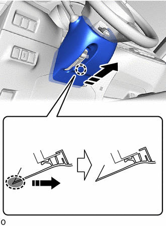
(a) Release the tilt and telescopic lever and fully extend and lower the steering column assembly.
(b) Lock the tilt and telescopic lever.
|
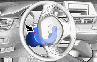
(c) Turn the steering wheel assembly to the left and remove the screw. |
|
|
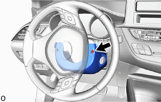
(d) Turn the steering wheel assembly to the right and remove the screw. |
|
(e) Push the lower steering column cover and disengage the claws as shown in the illustration.
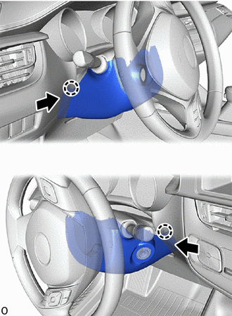
.png) |
Push |
|
(f) Disengage the claws. |
|
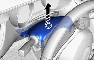
(g) Release the tilt and telescopic lever and fully extend and lift the steering column assembly.
(h) Lock the tilt and telescopic lever.
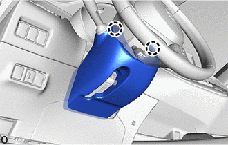
(i) Pull the lower steering column cover toward the rear of the vehicle to disengage the claw and remove the lower steering column cover.
.png) |
Place Hand Here |
.png) |
Remove in this Direction |
2. REMOVE UPPER STEERING COLUMN COVER
(a) Release the tilt and telescopic lever and fully extend and lower the steering column assembly.
(b) Lock the tilt and telescopic lever.
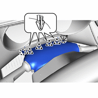
(c) Disengage the claw to separate the upper steering column cover as shown in the illustration.
|
|
Separate in this Direction |
|
(d) Disengage the claws and clips to remove the upper steering column cover from the lower instrument cover sub-assembly. |
|
3. REMOVE WINDSHIELD WIPER SWITCH ASSEMBLY
|
(a) Disconnect the 2 connectors. |
|
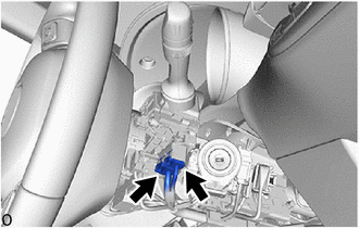
(b) Using a screwdriver with its tip wrapped in protective tape, disengage the claw and remove the windshield wiper switch assembly as shown in the illustration.
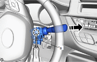
|
*a |
Protective Tape |
|
|
Remove in this Direction |
NOTICE:
If the claw is pulled with excessive force, it may break.
 Inspection
INSPECTION
PROCEDURE
1. INSPECT WINDSHIELD WIPER SWITCH ASSEMBLY
(a) Measure the resistance according to the value(s) in the table below.
Standard Resistance:
Front Wiper Switch
...
 Installation
INSTALLATION
PROCEDURE
1. INSTALL WINDSHIELD WIPER SWITCH ASSEMBLY
(a) Engage the claw to install the windshield wiper switch assembly as shown
in the illustration.
Install ...
Other materials:
Toyota CH-R Service Manual > Can Communication System: Check Bus 3 Line for Short to +B
DESCRIPTION
There may be a short circuit between one of the CAN bus lines and +B when no
resistance exists between terminal 6 (CA3H) of the central gateway ECU (network
gateway ECU) and terminal 16 (BAT) of the DLC3, or terminal 21 (CA3L) of the central
gateway ECU (network gateway ECU) and t ...
Toyota CH-R Service Manual > Audio And Visual System(for Radio Receiver Type): Steering Pad Switch Circuit
DESCRIPTION
This circuit sends an operation signal from the steering pad switch assembly
to the radio receiver assembly.
If there is an open in the circuit, the audio system cannot be operated using
the steering pad switch assembly.
If there is a short in the circuit, the same condition as wh ...
Toyota C-HR (AX20) 2023-2026 Owner's Manual
Toyota CH-R Owners Manual
- For safety and security
- Instrument cluster
- Operation of each component
- Driving
- Interior features
- Maintenance and care
- When trouble arises
- Vehicle specifications
- For owners
Toyota CH-R Service Manual
- Introduction
- Maintenance
- Audio / Video
- Cellular Communication
- Navigation / Multi Info Display
- Park Assist / Monitoring
- Brake (front)
- Brake (rear)
- Brake Control / Dynamic Control Systems
- Brake System (other)
- Parking Brake
- Axle And Differential
- Drive Shaft / Propeller Shaft
- K114 Cvt
- 3zr-fae Battery / Charging
- Networking
- Power Distribution
- Power Assist Systems
- Steering Column
- Steering Gear / Linkage
- Alignment / Handling Diagnosis
- Front Suspension
- Rear Suspension
- Tire / Wheel
- Tire Pressure Monitoring
- Door / Hatch
- Exterior Panels / Trim
- Horn
- Lighting (ext)
- Mirror (ext)
- Window / Glass
- Wiper / Washer
- Door Lock
- Heating / Air Conditioning
- Interior Panels / Trim
- Lighting (int)
- Meter / Gauge / Display
- Mirror (int)
- Power Outlets (int)
- Pre-collision
- Seat
- Seat Belt
- Supplemental Restraint Systems
- Theft Deterrent / Keyless Entry

0.0093