Toyota CH-R Service Manual: Installation
INSTALLATION
CAUTION / NOTICE / HINT
HINT:
- Use the same procedure for the RH side and LH side.
- The following procedure is for the LH side.
PROCEDURE
1. TEMPORARILY INSTALL REAR AXLE CARRIER SUB-ASSEMBLY
|
(a) Temporarily install the rear axle carrier sub-assembly to the rear upper control arm assembly with the bolt and nut. NOTICE:
|
|
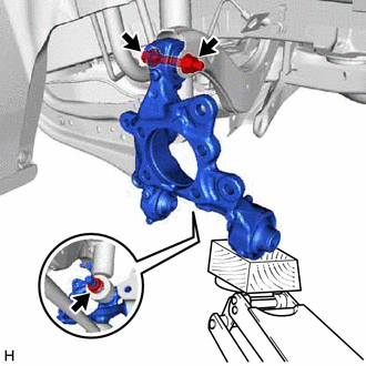
(b) Temporarily install the rear shock absorber assembly to the rear axle carrier sub-assembly with the nut.
NOTICE:
Hold the rear axle carrier pin while rotating the nut.
(c) Install the rear trailing arm assembly to the rear axle carrier sub-assembly with the 2 bolts.
Torque:
135 N·m {1377 kgf·cm, 100 ft·lbf}
2. INSTALL FLEXIBLE HOSE BRACKET
(a) Install the flexible hose bracket to the rear axle carrier sub-assembly with the bolt.
Torque:
29 N·m {296 kgf·cm, 21 ft·lbf}
3. TEMPORARILY INSTALL REAR NO. 1 SUSPENSION ARM ASSEMBLY
Click here
.gif)
4. INSTALL REAR LOWER COIL SPRING INSULATOR
Click here
5. INSTALL REAR COIL SPRING
Click here
6. STABILIZE SUSPENSION
Click here
7. INSTALL REAR UPPER CONTROL ARM ASSEMBLY
(a) Install the rear upper control arm assembly to the rear axle carrier sub-assembly with the bolt.
Torque:
73 N·m {744 kgf·cm, 54 ft·lbf}
NOTICE:
Because the nut has its own stopper, do not turn the nut. Tighten the bolt with the nut secured.
8. INSTALL REAR NO. 1 SUSPENSION ARM ASSEMBLY
Click here
9. INSTALL REAR NO. 2 SUSPENSION ARM ASSEMBLY
(a) Install the rear No. 2 suspension arm assembly (rear axle carrier sub-assembly side) with the bolt.
Click here
10. INSTALL REAR SHOCK ABSORBER ASSEMBLY
Click here
11. INSTALL REAR STABILIZER LINK ASSEMBLY
Click here
12. INSTALL REAR AXLE HUB AND BEARING ASSEMBLY
Click here
13. CONNECT SKID CONTROL SENSOR WIRE
Click here
14. INSTALL REAR DISC
Click here
15. INSTALL REAR DISC BRAKE CALIPER ASSEMBLY
Click here
16. INSTALL REAR HEIGHT CONTROL SENSOR SUB-ASSEMBLY LH (w/ Height Control Sensor)
Click here
17. INSTALL REAR WHEEL
Click here
18. INSTALL REAR NO. 2 SUSPENSION ARM ASSEMBLY
(a) Install the rear No. 2 suspension arm assembly (rear suspension member sub-assembly side) with the nut.
Click here
19. INSPECT AND ADJUST REAR WHEEL ALIGNMENT
Click here
20. CHECK FOR SPEED SENSOR SIGNAL
Click here
21. PERFORM INITIALIZATION (w/ Height Control Sensor)
Click here
 Removal
REMOVAL
CAUTION / NOTICE / HINT
The necessary procedures (adjustment, calibration, initialization, or registration)
that must be performed after parts are removed and installed, or replaced during ...
 Rear Axle Hub
...
Other materials:
Toyota CH-R Service Manual > Fuel Lid Opener Switch: Removal
REMOVAL
PROCEDURE
1. REMOVE FRONT DOOR SCUFF PLATE LH
Click here
2. REMOVE COWL SIDE TRIM BOARD LH
Click here
3. REMOVE NO. 1 INSTRUMENT PANEL UNDER COVER SUB-ASSEMBLY
Click here
4. REMOVE INSTRUMENT CLUSTER FINISH PANEL GARNISH ASSEMBLY
Click here
5. REMOVE INSTRUM ...
Toyota CH-R Service Manual > Lighting System: How To Proceed With Troubleshooting
CAUTION / NOTICE / HINT
HINT:
Use the following procedure to troubleshoot the lighting system.
*: Use the Techstream.
PROCEDURE
1.
VEHICLE BROUGHT TO WORKSHOP
NEXT
...
Toyota C-HR (AX20) 2023-2026 Owner's Manual
Toyota CH-R Owners Manual
- For safety and security
- Instrument cluster
- Operation of each component
- Driving
- Interior features
- Maintenance and care
- When trouble arises
- Vehicle specifications
- For owners
Toyota CH-R Service Manual
- Introduction
- Maintenance
- Audio / Video
- Cellular Communication
- Navigation / Multi Info Display
- Park Assist / Monitoring
- Brake (front)
- Brake (rear)
- Brake Control / Dynamic Control Systems
- Brake System (other)
- Parking Brake
- Axle And Differential
- Drive Shaft / Propeller Shaft
- K114 Cvt
- 3zr-fae Battery / Charging
- Networking
- Power Distribution
- Power Assist Systems
- Steering Column
- Steering Gear / Linkage
- Alignment / Handling Diagnosis
- Front Suspension
- Rear Suspension
- Tire / Wheel
- Tire Pressure Monitoring
- Door / Hatch
- Exterior Panels / Trim
- Horn
- Lighting (ext)
- Mirror (ext)
- Window / Glass
- Wiper / Washer
- Door Lock
- Heating / Air Conditioning
- Interior Panels / Trim
- Lighting (int)
- Meter / Gauge / Display
- Mirror (int)
- Power Outlets (int)
- Pre-collision
- Seat
- Seat Belt
- Supplemental Restraint Systems
- Theft Deterrent / Keyless Entry

0.0132