Toyota CH-R Service Manual: Removal
REMOVAL
CAUTION / NOTICE / HINT
The necessary procedures (adjustment, calibration, initialization, or registration) that must be performed after parts are removed and installed, or replaced during rear axle carrier sub-assembly removal/installation are shown below.
Necessary Procedures After Parts Removed/Installed/Replaced|
Replaced Part or Performed Procedure |
Necessary Procedure |
Effect/Inoperative Function when Necessary Procedure not Performed |
Link |
|---|---|---|---|
|
Rear wheel alignment adjustment |
|
|
|
|
Removal/installation of rear height control sensor sub-assembly LH*1 |
Initialize headlight ECU sub-assembly LH |
Automatic headlight beam level control system |
|
|
Suspension, tires, etc. (The vehicle height changes because of suspension or tire replacement)*1 |
- *1: w/ Height Control Sensor
HINT:
- Use the same procedure for the RH side and LH side.
- The following procedure is for the LH side.
PROCEDURE
1. REMOVE REAR WHEEL
Click here
.gif)
2. SEPARATE REAR DISC BRAKE CALIPER ASSEMBLY
Click here
3. REMOVE REAR DISC
Click here
4. DISCONNECT SKID CONTROL SENSOR WIRE
Click here
5. REMOVE REAR AXLE HUB AND BEARING ASSEMBLY
Click here
6. REMOVE FLEXIBLE HOSE BRACKET
|
(a) Remove the bolt and flexible hose bracket from the rear axle carrier sub-assembly. |
|
7. REMOVE REAR HEIGHT CONTROL SENSOR SUB-ASSEMBLY LH (w/ Height Control Sensor)
Click here
8. REMOVE REAR STABILIZER LINK ASSEMBLY
Click here
9. REMOVE REAR COIL SPRING
Click here
10. REMOVE REAR LOWER COIL SPRING INSULATOR
Click here
11. REMOVE REAR NO. 1 SUSPENSION ARM ASSEMBLY
Click here
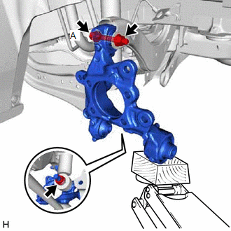
12. REMOVE REAR AXLE CARRIER SUB-ASSEMBLY
|
(a) Loosen the 2 bolts of the rear trailing arm assembly. |
|
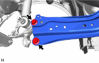
|
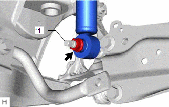
(b) Loosen the nut of the rear shock absorber assembly. NOTICE: Hold the rear axle carrier pin while rotating the nut. |
|
|
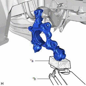
(c) Using a jack and a wooden block, support the rear axle carrier sub-assembly. NOTICE:
|
|
|
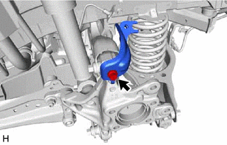
(d) Loosen the bolt (A). NOTICE: Because the nut has its own stopper, do not turn the nut. Loosen the bolt with the nut secured. |
|
(e) Remove the 2 bolts and separate the rear trailing arm assembly from the rear axle carrier sub-assembly.
(f) Remove the nut and separate the rear shock absorber assembly from the rear axle carrier sub-assembly.
NOTICE:
Hold the rear axle carrier pin while rotating the nut.
(g) Remove the bolt (A), nut and rear axle carrier sub-assembly from the rear upper control arm assembly.
NOTICE:
Because the nut has its own stopper, do not turn the nut. Loosen the bolt with the nut secured.
 Components
COMPONENTS
ILLUSTRATION
*1
REAR AXLE HUB AND BEARING ASSEMBLY
*2
REAR DISC
*3
REAR DISC BRAKE CALIPER ASSEMBLY
*4 ...
 Installation
INSTALLATION
CAUTION / NOTICE / HINT
HINT:
Use the same procedure for the RH side and LH side.
The following procedure is for the LH side.
PROCEDURE
1. TEMPORARILY INSTALL REAR ...
Other materials:
Toyota CH-R Service Manual > Smart Key System(for Start Function): Operation Check
OPERATION CHECK
NOTICE:
Make sure that the smart key system (for Start Function) has not been canceled
before performing this inspection.
Click here
OPERATION DESCRIPTION
(a) Push-button start function:
(1) When the electrical key transmitter sub-assembly is in a vehicle interior
detecti ...
Toyota CH-R Service Manual > Glove Box Light: Removal
REMOVAL
PROCEDURE
1. REMOVE REAR CONSOLE BOX ASSEMBLY
Click here
2. REMOVE FRONT DOOR SCUFF PLATE RH
HINT:
Use the same procedure as for the LH side.
Click here
3. REMOVE COWL SIDE TRIM BOARD RH
HINT:
Use the same procedure as for the LH side.
Click here
4. REMOVE NO. 2 INSTR ...
Toyota C-HR (AX20) 2023-2026 Owner's Manual
Toyota CH-R Owners Manual
- For safety and security
- Instrument cluster
- Operation of each component
- Driving
- Interior features
- Maintenance and care
- When trouble arises
- Vehicle specifications
- For owners
Toyota CH-R Service Manual
- Introduction
- Maintenance
- Audio / Video
- Cellular Communication
- Navigation / Multi Info Display
- Park Assist / Monitoring
- Brake (front)
- Brake (rear)
- Brake Control / Dynamic Control Systems
- Brake System (other)
- Parking Brake
- Axle And Differential
- Drive Shaft / Propeller Shaft
- K114 Cvt
- 3zr-fae Battery / Charging
- Networking
- Power Distribution
- Power Assist Systems
- Steering Column
- Steering Gear / Linkage
- Alignment / Handling Diagnosis
- Front Suspension
- Rear Suspension
- Tire / Wheel
- Tire Pressure Monitoring
- Door / Hatch
- Exterior Panels / Trim
- Horn
- Lighting (ext)
- Mirror (ext)
- Window / Glass
- Wiper / Washer
- Door Lock
- Heating / Air Conditioning
- Interior Panels / Trim
- Lighting (int)
- Meter / Gauge / Display
- Mirror (int)
- Power Outlets (int)
- Pre-collision
- Seat
- Seat Belt
- Supplemental Restraint Systems
- Theft Deterrent / Keyless Entry

0.0082