Toyota CH-R Service Manual: Inspection
INSPECTION
PROCEDURE
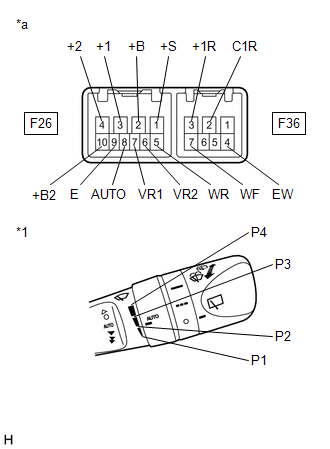
1. INSPECT WINDSHIELD WIPER SWITCH ASSEMBLY
|
(a) Measure the resistance according to the value(s) in the table below. Standard Resistance: Front Wiper Switch
HINT: *: The rain sensor sensitivity can be adjusted by the windshield wiper switch adjusting ring. If the result is not as specified, replace the windshield wiper switch assembly. |
|
 On-vehicle Inspection
ON-VEHICLE INSPECTION
PROCEDURE
1. INSPECT WINDSHIELD WIPER SWITCH ASSEMBLY
(a) Check the front washer operation.
(1) Connect a voltmeter positive (+) lead to terminal F36-7 (WF) and
...
 Removal
REMOVAL
PROCEDURE
1. REMOVE LOWER STEERING COLUMN COVER
NOTICE:
Removing the lower steering column cover in the incorrect order will cause the
parts to break.
(a) Release the tilt and telescopi ...
Other materials:
Toyota CH-R Service Manual > Seat Belt Warning System(w/o Occupant Classification System): Front Passenger Side Seat Belt Warning Light Malfunction
DESCRIPTION
When the ignition switch is ON, the combination meter assembly monitors the state
of the front passenger side seat and the front seat inner belt assembly (front passenger
seat) and also whether the front passenger seat is occupied. If the front passenger
side seat belt is not fast ...
Toyota CH-R Service Manual > Front Lower Suspension Arm: Installation
INSTALLATION
PROCEDURE
1. INSTALL FRONT LOWER NO. 1 SUSPENSION ARM SUB-ASSEMBLY
(a) Temporarily install the front lower No. 1 suspension arm sub-assembly LH
to the front suspension crossmember sub-assembly with the 2 bolts and nut.
(b) Install the front lower No. 1 suspension arm sub-assembly ...
Toyota C-HR (AX20) 2023-2026 Owner's Manual
Toyota CH-R Owners Manual
- For safety and security
- Instrument cluster
- Operation of each component
- Driving
- Interior features
- Maintenance and care
- When trouble arises
- Vehicle specifications
- For owners
Toyota CH-R Service Manual
- Introduction
- Maintenance
- Audio / Video
- Cellular Communication
- Navigation / Multi Info Display
- Park Assist / Monitoring
- Brake (front)
- Brake (rear)
- Brake Control / Dynamic Control Systems
- Brake System (other)
- Parking Brake
- Axle And Differential
- Drive Shaft / Propeller Shaft
- K114 Cvt
- 3zr-fae Battery / Charging
- Networking
- Power Distribution
- Power Assist Systems
- Steering Column
- Steering Gear / Linkage
- Alignment / Handling Diagnosis
- Front Suspension
- Rear Suspension
- Tire / Wheel
- Tire Pressure Monitoring
- Door / Hatch
- Exterior Panels / Trim
- Horn
- Lighting (ext)
- Mirror (ext)
- Window / Glass
- Wiper / Washer
- Door Lock
- Heating / Air Conditioning
- Interior Panels / Trim
- Lighting (int)
- Meter / Gauge / Display
- Mirror (int)
- Power Outlets (int)
- Pre-collision
- Seat
- Seat Belt
- Supplemental Restraint Systems
- Theft Deterrent / Keyless Entry

0.0104