Toyota CH-R Service Manual: Open or Short Circuit in Motor (C13A6)
DESCRIPTION
|
DTC No. |
Detection Item |
DTC Detection Condition |
Trouble Area |
Memory |
Note |
|---|---|---|---|---|---|
|
C13A6 |
Open or Short Circuit in Motor |
Parking brake actuator assembly open or short circuit is detected for 0.015 seconds or more. |
|
DTC stored |
An electric parking brake system malfunction is displayed on the multi-information display. |
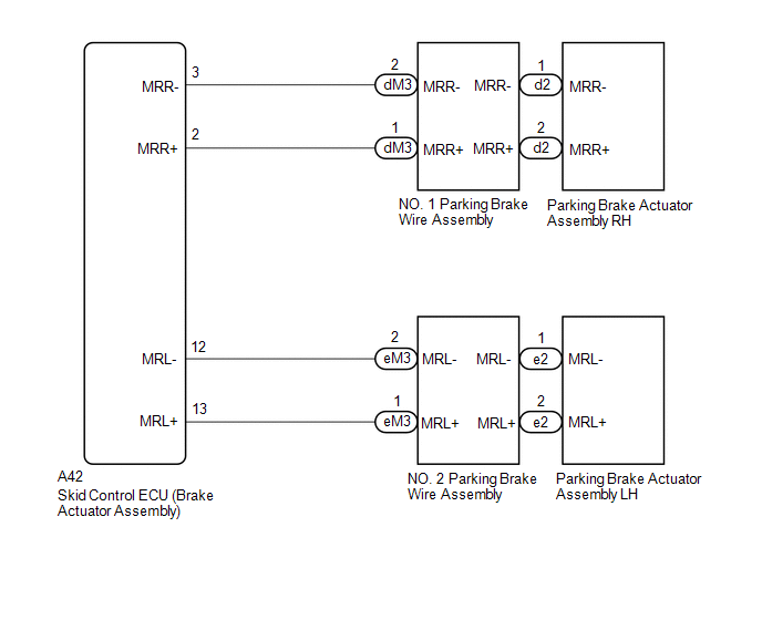
WIRING DIAGRAM
CAUTION / NOTICE / HINT
NOTICE:
- The electric parking brake may still operate up to 20 seconds after the ignition switch is turned off. Before disconnecting connectors or fuses, turn the ignition switch off and wait 20 seconds or more.
- When replacing the skid control ECU (brake actuator assembly), operate the electric parking brake switch (electric parking brake switch assembly) as the parking brake indicator light blinks (red) when the ignition switch is first turned to ON.
PROCEDURE
|
1. |
READ VALUE USING TECHSTREAM (PERMISSION OF RH INTERLOCKING PKB LOCK / PERMISSION OF LH INTERLOCKING PKB LOCK) |
(a) Turn the ignition switch off.
(b) Connect the Techstream to the DLC3.
(c) Turn the ignition switch to ON.
(d) Turn the Techstream on.
(e) Enter the following menus: Chassis / Electric Parking Brake / Data List.
(f) Read the Data List according to the display on the Techstream.
Chassis > ABS/VSC/TRAC/EPB > Data List|
Tester Display |
Measurement Item |
Range |
Normal Condition |
Diagnostic Note |
|---|---|---|---|---|
|
Permission of RH Interlocking PKB Lock |
Parking brake actuator assembly RH parking brake lock control permission status |
OK or NG |
- |
- |
|
Permission of LH Interlocking PKB Lock |
Parking brake actuator assembly LH parking brake lock control permission status |
OK or NG |
- |
- |
|
Tester Display |
|---|
|
Permission of RH Interlocking PKB Lock |
|
Permission of LH Interlocking PKB Lock |
|
.gif)
|
2. |
INSPECT PARKING BRAKE WIRE ASSEMBLY |
.png)
|
*a |
Front view of Parking Brake Wire Assembly |
*b |
(to wire harness connector) |
|
*c |
(to Parking Brake Actuator Assembly) |
*d |
for RH |
|
*e |
for LH |
- |
- |
(a) Remove the parking brake wire assembly.
Click here
.gif)
(b) Check the parking brake wire assembly for damage.
OK:
No damage.
HINT:
If damaged, there may be a short in the wire harness or a short to ground.
(c) Inspect the parking brake wire assembly.
Standard Resistance:
for RH|
Tester Connection |
Condition |
Specified Condition |
|---|---|---|
|
dM3-2 (MRR-) - d2-1 (MRR-) |
Always |
Below 1 Ω |
|
dM3-2 (MRR-) - d2-2 (MRR+) |
Always |
10 kΩ or higher |
|
dM3-2 (MRR-) or d2-1 (MRR-) - Body ground |
Always |
10 kΩ or higher |
|
dM3-1 (MRR+) - d2-2 (MRR+) |
Always |
Below 1 Ω |
|
dM3-1 (MRR+) - d2-1 (MRR-) |
Always |
10 kΩ or higher |
|
dM3-1 (MRR+) or d2-2 (MRR+) - Body ground |
Always |
10 kΩ or higher |
|
Tester Connection |
Condition |
Specified Condition |
|---|---|---|
|
eM3-2 (MRL-) - e2-1 (MRL-) |
Always |
Below 1 Ω |
|
eM3-2 (MRL-) - e2-2 (MRL+) |
Always |
10 kΩ or higher |
|
eM3-2 (MRL-) or e2-1 (MRL-) - Body ground |
Always |
10 kΩ or higher |
|
eM3-1 (MRL+) - e2-2 (MRL+) |
Always |
Below 1 Ω |
|
eM3-1 (MRL+) - e2-1 (MRL-) |
Always |
10 kΩ or higher |
|
eM3-1 (MRL+) or e2-2 (MRL+) - Body ground |
Always |
10 kΩ or higher |
| NG | .gif) |
REPLACE PARKING BRAKE WIRE ASSEMBLY |
|
|
3. |
CHECK HARNESS AND CONNECTOR (SKID CONTROL ECU (BRAKE ACTUATOR ASSEMBLY) - PARKING BRAKE ACTUATOR ASSEMBLY) |
(a) Turn the ignition switch off.
(b) Make sure the parking brake wire assembly is securely installed.
(c) Disconnect the A42 skid control ECU (brake actuator assembly) connector.
(d) Disconnect the d2*1 or e2*2 parking brake actuator assembly connector.
- *1: for RH
- *2: for LH
(e) Measure the resistance according to the value(s) in the table below.
Standard Resistance:
for RH|
Tester Connection |
Condition |
Specified Condition |
|---|---|---|
|
A42-2 (MRR+) - d2-2 (MRR+) |
Always |
Below 1 Ω |
|
A42-3 (MRR-) - d2-1 (MRR-) |
Always |
Below 1 Ω |
|
A42-2 (MRR+) or d2-2 (MRR+) - Body ground |
Always |
10 kΩ or higher |
|
A42-3 (MRR-) or d2-1 (MRR-) - Body ground |
Always |
10 kΩ or higher |
|
Tester Connection |
Condition |
Specified Condition |
|---|---|---|
|
A42-13 (MRL+) - e2-2 (MRL+) |
Always |
Below 1 Ω |
|
A42-12 (MRL-) - e2-1 (MRL-) |
Always |
Below 1 Ω |
|
A42-13 (MRL+) or e2-2 (MRL+) - Body ground |
Always |
10 kΩ or higher |
|
A42-12 (MRL-) or e2-1 (MRL-) - Body ground |
Always |
10 kΩ or higher |
| NG | |
REPAIR OR REPLACE HARNESS OR CONNECTOR |
|
|
4. |
INSPECT PARKING BRAKE ACTUATOR ASSEMBLY |
(a) Inspect the parking brake actuator assembly.
Click here
| OK | |
REPLACE SKID CONTROL ECU (BRAKE ACTUATOR ASSEMBLY) |
| NG | |
REPLACE PARKING BRAKE ACTUATOR ASSEMBLY |
 EPB Switch Malfunction (C13B4)
DESCRIPTION
When the electric parking brake switch is pulled, a lock request signal is sent
from the skid control ECU (brake actuator assembly) to the parking brake actuator
assembly. When the el ...
 Electric Parking Brake does not Operate
WIRING DIAGRAM
CAUTION / NOTICE / HINT
NOTICE:
Inspect the fuses for circuits related to this system before performing
the following inspection procedure.
The electric parking bra ...
Other materials:
Toyota CH-R Service Manual > Rear Door Outside Moulding: Disassembly
DISASSEMBLY
CAUTION / NOTICE / HINT
HINT:
Use the same procedure for the RH and LH sides.
The procedure listed below is for the LH side.
PROCEDURE
1. REMOVE REAR DOOR UPPER OUTSIDE MOULDING PAD
(a) Remove the rear door upper outside moulding pad.
...
Toyota CH-R Service Manual > Airbag System: Occupant Classification System Malfunction (B1650/32,B165A/32)
DESCRIPTION
The airbag sensor assembly and occupant detection ECU communicate via CAN communication.
When the occupant detection ECU stores DTC B1771, B1780, B1782, B1795, B1798,
B1799, U0125 or U0129, the airbag sensor assembly receives this information and
stores DTC B1650/32.
When the occu ...
Toyota C-HR (AX20) 2023-2026 Owner's Manual
Toyota CH-R Owners Manual
- For safety and security
- Instrument cluster
- Operation of each component
- Driving
- Interior features
- Maintenance and care
- When trouble arises
- Vehicle specifications
- For owners
Toyota CH-R Service Manual
- Introduction
- Maintenance
- Audio / Video
- Cellular Communication
- Navigation / Multi Info Display
- Park Assist / Monitoring
- Brake (front)
- Brake (rear)
- Brake Control / Dynamic Control Systems
- Brake System (other)
- Parking Brake
- Axle And Differential
- Drive Shaft / Propeller Shaft
- K114 Cvt
- 3zr-fae Battery / Charging
- Networking
- Power Distribution
- Power Assist Systems
- Steering Column
- Steering Gear / Linkage
- Alignment / Handling Diagnosis
- Front Suspension
- Rear Suspension
- Tire / Wheel
- Tire Pressure Monitoring
- Door / Hatch
- Exterior Panels / Trim
- Horn
- Lighting (ext)
- Mirror (ext)
- Window / Glass
- Wiper / Washer
- Door Lock
- Heating / Air Conditioning
- Interior Panels / Trim
- Lighting (int)
- Meter / Gauge / Display
- Mirror (int)
- Power Outlets (int)
- Pre-collision
- Seat
- Seat Belt
- Supplemental Restraint Systems
- Theft Deterrent / Keyless Entry

0.0069