Toyota CH-R Service Manual: EPB Switch Malfunction (C13B4)
DESCRIPTION
When the electric parking brake switch is pulled, a lock request signal is sent from the skid control ECU (brake actuator assembly) to the parking brake actuator assembly. When the electric parking brake switch is pushed, a release request signal is sent from the skid control ECU (brake actuator assembly) to the parking brake actuator assembly.
|
DTC No. |
Detection Item |
DTC Detection Condition |
Trouble Area |
Memory |
Note |
|---|---|---|---|---|---|
|
C13B4 |
EPB Switch Malfunction |
|
|
DTC stored |
An electric parking brake system malfunction is displayed on the multi-information display. |
|
Vehicle Condition |
|||||
|---|---|---|---|---|---|
|
Pattern 1 |
Pattern 2 |
Pattern 3 |
Pattern 4 |
||
|
Diagnosis Condition |
- |
- |
- |
- |
- |
|
Malfunction Status |
Parking brake switch power supply voltage from the +BS terminal less than 7 V |
○ |
- |
- |
- |
|
Parking brake switch open circuit is detected |
- |
○ |
- |
- |
|
|
Parking brake switch short circuit is detected |
- |
- |
○ |
- |
|
|
Parking brake switch stuck malfunction |
- |
- |
- |
○ |
|
|
Detection Time |
1 second or more |
0.3 seconds or more |
0.3 seconds or more |
- |
|
|
Number of Trips |
1 trip |
1 trip |
1 trip |
1 trip |
|
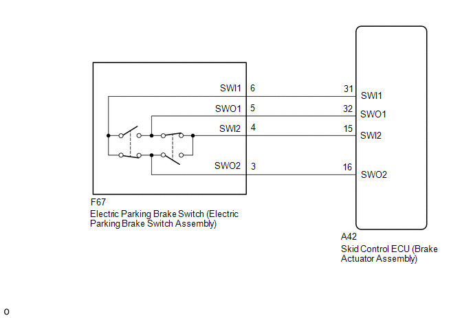
WIRING DIAGRAM
CAUTION / NOTICE / HINT
NOTICE:
- The electric parking brake may still operate up to 20 seconds after the ignition switch is turned off. Before disconnecting connectors or fuses, turn the ignition switch off and wait 20 seconds or more.
- When replacing the skid control ECU (brake actuator assembly), operate the electric parking brake switch (electric parking brake switch assembly) as the parking brake indicator light (red) blinks when the ignition switch is first turned to ON.
PROCEDURE
|
1. |
INSPECT ELECTRIC PARKING BRAKE SWITCH (ELECTRIC PARKING BRAKE SWITCH ASSEMBLY) |
(a) Inspect the electric parking brake switch (electric parking brake switch assembly).
Click here
.gif)
| NG | .gif) |
REPLACE ELECTRIC PARKING BRAKE SWITCH (ELECTRIC PARKING BRAKE SWITCH ASSEMBLY) |
|
.gif)
|
2. |
CHECK HARNESS AND CONNECTOR (SKID CONTROL ECU (BRAKE ACTUATOR ASSEMBLY) - ELECTRIC PARKING BRAKE SWITCH (ELECTRIC PARKING BRAKE SWITCH ASSEMBLY)) |
(a) Disconnect the F67 electric parking brake switch (electric parking brake switch assembly) connector.
(b) Disconnect the A42 skid control ECU (brake actuator assembly) connector.
(c) Measure the resistance according to the value(s) in the table below.
Standard Resistance:
|
Tester Connection |
Condition |
Specified Condition |
|---|---|---|
|
A42-31 (SWI1) - F67-6 (SWI1) |
Always |
Below 5 Ω |
|
A42-32 (SWO1) - F67-5 (SWO1) |
Always |
Below 5 Ω |
|
A42-15 (SWI2) - F67-4 (SWI2) |
Always |
Below 5 Ω |
|
A42-16 (SWO2) - F67-3 (SWO2) |
Always |
Below 5 Ω |
|
A42-31 (SWI1) or F67-6 (SWI1) - Body ground |
Always |
10 kΩ or higher |
|
A42-32 (SWO1) or F67-5 (SWO1) - Body ground |
Always |
10 kΩ or higher |
|
A42-15 (SWI2) or F67-4 (SWI2) - Body ground |
Always |
10 kΩ or higher |
|
A42-16 (SWO2) or F67-3 (SWO2) - Body ground |
Always |
10 kΩ or higher |
| NG | |
REPAIR OR REPLACE HARNESS OR CONNECTOR |
|
|
3. |
CHECK DTC |
(a) Clear the DTCs.
Click here
(b) Turn the ignition switch off.
(c) Turn the ignition switch to ON.
(d) Check for DTCs.
Click here
|
Result |
Proceed to |
|---|---|
|
DTCs are output |
A |
|
DTCs are not output |
B |
| A | |
REPLACE SKID CONTROL ECU (BRAKE ACTUATOR ASSEMBLY) |
| B | |
USE SIMULATION METHOD TO CHECK
|
 Actuator Malfunction (C13A7)
DESCRIPTION
DTC No.
Detection Item
DTC Detection Condition
Trouble Area
Memory
Note
C13A7
Actuator Malfun ...
 Open or Short Circuit in Motor (C13A6)
DESCRIPTION
DTC No.
Detection Item
DTC Detection Condition
Trouble Area
Memory
Note
C13A6
Open or Short C ...
Other materials:
Toyota CH-R Service Manual > Occupant Classification System: Dtc Check / Clear
DTC CHECK / CLEAR
DTC CHECK
(a) Turn the ignition switch off.
(b) Connect the Techstream to the DLC3.
(c) Turn the ignition switch to ON, and wait for at least 10 seconds.
(d) Turn the Techstream on.
(e) Enter the following menus: Body Electrical / Occupant Detection / Trouble
Codes.
Body E ...
Toyota CH-R Service Manual > Lighting System: System Diagram
SYSTEM DIAGRAM
HEADLIGHT ASSEMBLY (for LED Headlight)
...
Toyota C-HR (AX20) 2023-2026 Owner's Manual
Toyota CH-R Owners Manual
- For safety and security
- Instrument cluster
- Operation of each component
- Driving
- Interior features
- Maintenance and care
- When trouble arises
- Vehicle specifications
- For owners
Toyota CH-R Service Manual
- Introduction
- Maintenance
- Audio / Video
- Cellular Communication
- Navigation / Multi Info Display
- Park Assist / Monitoring
- Brake (front)
- Brake (rear)
- Brake Control / Dynamic Control Systems
- Brake System (other)
- Parking Brake
- Axle And Differential
- Drive Shaft / Propeller Shaft
- K114 Cvt
- 3zr-fae Battery / Charging
- Networking
- Power Distribution
- Power Assist Systems
- Steering Column
- Steering Gear / Linkage
- Alignment / Handling Diagnosis
- Front Suspension
- Rear Suspension
- Tire / Wheel
- Tire Pressure Monitoring
- Door / Hatch
- Exterior Panels / Trim
- Horn
- Lighting (ext)
- Mirror (ext)
- Window / Glass
- Wiper / Washer
- Door Lock
- Heating / Air Conditioning
- Interior Panels / Trim
- Lighting (int)
- Meter / Gauge / Display
- Mirror (int)
- Power Outlets (int)
- Pre-collision
- Seat
- Seat Belt
- Supplemental Restraint Systems
- Theft Deterrent / Keyless Entry

0.0119