Toyota CH-R Service Manual: Actuator Malfunction (C13A7)
DESCRIPTION
|
DTC No. |
Detection Item |
DTC Detection Condition |
Trouble Area |
Memory |
Note |
|---|---|---|---|---|---|
|
C13A7 |
Actuator Malfunction |
When the electric parking brake is operating, motor lock, gear lock, motor spinning or repeated slipping occurs. |
|
DTC stored |
An electric parking brake system malfunction is displayed on the multi-information display. |
WIRING DIAGRAM
Click here
.gif)
CAUTION / NOTICE / HINT
NOTICE:
- This DTC may be stored when the system changes to pad replacement mode, but this is not a malfunction.
- This DTC may be stored when the parking brake is forcibly released, but this is not a malfunction.
- The electric parking brake may still operate up to 20 seconds after the ignition switch is turned off. Before disconnecting connectors or fuses, turn the ignition switch off and wait 20 seconds or more.
- When replacing the skid control ECU (brake actuator assembly), operate the electric parking brake switch (electric parking brake switch assembly) as the parking brake indicator light (red) blinks when the ignition switch is first turned to ON.
PROCEDURE
|
1. |
CHECK DTC |
(a) Check for DTCs.
Click here
|
Result |
Proceed to |
|---|---|
|
Only DTC C13A7 is output |
A |
|
DTCs other than C13A7 are output |
B |
| B | .gif) |
GO TO DIAGNOSTIC TROUBLE CODE CHART |
|
.gif)
|
2. |
READ VALUE USING TECHSTREAM (PERMISSION OF RH INTERLOCKING PKB LOCK / PERMISSION OF LH INTERLOCKING PKB LOCK) |
(a) Turn the ignition switch off.
(b) Connect the Techstream to the DLC3.
(c) Turn the ignition switch to ON.
(d) Turn the Techstream on.
(e) Enter the following menus: Chassis / Electric Parking Brake / Data List.
(f) Read the Data List according to the display on the Techstream.
Chassis > ABS/VSC/TRAC/EPB > Data List|
Tester Display |
Measurement Item |
Range |
Normal Condition |
Diagnostic Note |
|---|---|---|---|---|
|
Permission of RH Interlocking PKB Lock |
Parking brake actuator assembly RH parking brake lock control permission status |
OK or NG |
- |
- |
|
Permission of LH Interlocking PKB Lock |
Parking brake actuator assembly LH parking brake lock control permission status |
OK or NG |
- |
- |
|
Tester Display |
|---|
|
Permission of RH Interlocking PKB Lock |
|
Permission of LH Interlocking PKB Lock |
|
|
3. |
INSPECT PARKING BRAKE WIRE ASSEMBLY |
|
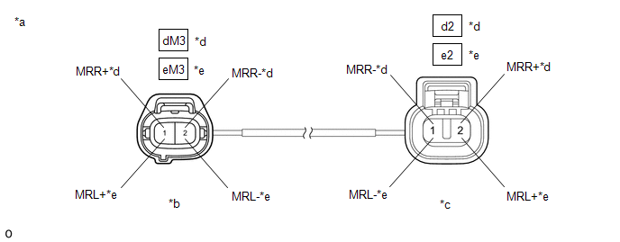
*a |
Front view of Parking Brake Wire Assembly |
*b |
(to wire harness connector) |
|
*c |
(to Parking Brake Actuator Assembly) |
*d |
for RH |
|
*e |
for LH |
- |
- |
(a) Remove the parking brake wire assembly.
Click here
(b) Check the parking brake wire assembly for damage.
OK:
No damage.
HINT:
If damaged, there may be a short in the wire harness or a short to ground.
(c) Inspect the parking brake wire assembly.
Standard Resistance:
for RH|
Tester Connection |
Condition |
Specified Condition |
|---|---|---|
|
dM3-2 (MRR-) - d2-1 (MRR-) |
Always |
Below 1 Ω |
|
dM3-2 (MRR-) - d2-2 (MRR+) |
Always |
10 kΩ or higher |
|
dM3-2 (MRR-) or d2-1 (MRR-) - Body ground |
Always |
10 kΩ or higher |
|
dM3-1 (MRR+) - d2-2 (MRR+) |
Always |
Below 1 Ω |
|
dM3-1 (MRR+) - d2-1 (MRR-) |
Always |
10 kΩ or higher |
|
dM3-1 (MRR+) or d2-2 (MRR+) - Body ground |
Always |
10 kΩ or higher |
|
Tester Connection |
Condition |
Specified Condition |
|---|---|---|
|
eM3-2 (MRL-) - e2-1 (MRL-) |
Always |
Below 1 Ω |
|
eM3-2 (MRL-) - e2-2 (MRL+) |
Always |
10 kΩ or higher |
|
eM3-2 (MRL-) or e2-1 (MRL-) - Body ground |
Always |
10 kΩ or higher |
|
eM3-1 (MRL+) - e2-2 (MRL+) |
Always |
Below 1 Ω |
|
eM3-1 (MRL+) - e2-1 (MRL-) |
Always |
10 kΩ or higher |
|
eM3-1 (MRL+) or e2-2 (MRL+) - Body ground |
Always |
10 kΩ or higher |
| NG | |
REPLACE PARKING BRAKE WIRE ASSEMBLY |
|
|
4. |
CHECK HARNESS AND CONNECTOR (SKID CONTROL ECU (BRAKE ACTUATOR ASSEMBLY) - PARKING BRAKE ACTUATOR ASSEMBLY) |
(a) Turn the ignition switch off.
(b) Make sure the parking brake wire assembly is securely installed.
(c) Disconnect the A42 skid control ECU (brake actuator assembly) connector.
(d) Disconnect the d2*1 or e2*2 parking brake actuator assembly connector.
- *1: for RH
- *2: for LH
(e) Measure the resistance according to the value(s) in the table below.
Standard Resistance:
for RH|
Tester Connection |
Condition |
Specified Condition |
|---|---|---|
|
A42-2 (MRR+) - d2-2 (MRR+) |
Always |
Below 1 Ω |
|
A42-3 (MRR-) - d2-1 (MRR-) |
Always |
Below 1 Ω |
|
A42-2 (MRR+) or d2-2 (MRR+) - Body ground |
Always |
10 kΩ or higher |
|
A42-3 (MRR-) or d2-1 (MRR-) - Body ground |
Always |
10 kΩ or higher |
|
Tester Connection |
Condition |
Specified Condition |
|---|---|---|
|
A42-13 (MRL+) - e2-2 (MRL+) |
Always |
Below 1 Ω |
|
A42-12 (MRL-) - e2-1 (MRL-) |
Always |
Below 1 Ω |
|
A42-13 (MRL+) or e2-2 (MRL+) - Body ground |
Always |
10 kΩ or higher |
|
A42-12 (MRL-) or e2-1 (MRL-) - Body ground |
Always |
10 kΩ or higher |
| NG | |
REPAIR OR REPLACE HARNESS OR CONNECTOR |
|
|
5. |
INSPECT REAR BRAKE AND PARKING BRAKE ACTUATOR ASSEMBLY |
(a) Enter rear brake pad replacement mode.
Click here
(b) Turn the ignition switch off.
(c) Check that the rotating parts are not seized or the actuator is not spinning freely.
(1) Check that the parking brake actuator assembly is installed properly to the rear brake caliper and that it is not spinning freely.
For the parking brake actuator assembly removal procedure: Click here
(2) Check that there is no damage to the rotating parts from the parking brake actuator assembly to the rear brake caliper.
(3) Inspect the parking brake actuator assembly and check that it operates correctly.
Click here
(4) Check that the rear brake caliper threaded part rotates and that the rear disc brake piston moves outward.
HINT:
For the check procedures, refer to the parking brake forced release method when not using the Techstream.
- for TMC Made
Click here
- for TMMT Made
Click here
HINT:
Return to normal mode after work is complete.
Click here
| OK | |
REPLACE PARKING BRAKE ACTUATOR ASSEMBLY |
| NG | |
REPAIR OR REPLACE NECESSARY PARTS |
 Electric Current of Motor (C13A5,C13B0)
DESCRIPTION
The following DTCs are stored when a malfunction occurs in the skid control ECU
(brake actuator assembly).
DTC No.
Detection Item
DTC Detection Conditi ...
 EPB Switch Malfunction (C13B4)
DESCRIPTION
When the electric parking brake switch is pulled, a lock request signal is sent
from the skid control ECU (brake actuator assembly) to the parking brake actuator
assembly. When the el ...
Other materials:
Toyota CH-R Service Manual > Seat Heater System: Parts Location
PARTS LOCATION
ILLUSTRATION
*1
NO. 2 ENGINE ROOM RELAY BLOCK
- S/HTR F/R FUSE
- S/HTR F/L FUSE
-
-
ILLUSTRATION
*A
for TMMT Made
*B
for TMC Made
*1
SEAT HEATER S ...
Toyota CH-R Service Manual > Lin Communication System: Diagnostic Trouble Code Chart
DIAGNOSTIC TROUBLE CODE CHART
LIN Communication System
DTC No.
Detection Item
Link
B1206
P/W Master Switch Communication Stop
B1249
Double Locking ECU Communication Stop
...
Toyota C-HR (AX20) 2023-2026 Owner's Manual
Toyota CH-R Owners Manual
- For safety and security
- Instrument cluster
- Operation of each component
- Driving
- Interior features
- Maintenance and care
- When trouble arises
- Vehicle specifications
- For owners
Toyota CH-R Service Manual
- Introduction
- Maintenance
- Audio / Video
- Cellular Communication
- Navigation / Multi Info Display
- Park Assist / Monitoring
- Brake (front)
- Brake (rear)
- Brake Control / Dynamic Control Systems
- Brake System (other)
- Parking Brake
- Axle And Differential
- Drive Shaft / Propeller Shaft
- K114 Cvt
- 3zr-fae Battery / Charging
- Networking
- Power Distribution
- Power Assist Systems
- Steering Column
- Steering Gear / Linkage
- Alignment / Handling Diagnosis
- Front Suspension
- Rear Suspension
- Tire / Wheel
- Tire Pressure Monitoring
- Door / Hatch
- Exterior Panels / Trim
- Horn
- Lighting (ext)
- Mirror (ext)
- Window / Glass
- Wiper / Washer
- Door Lock
- Heating / Air Conditioning
- Interior Panels / Trim
- Lighting (int)
- Meter / Gauge / Display
- Mirror (int)
- Power Outlets (int)
- Pre-collision
- Seat
- Seat Belt
- Supplemental Restraint Systems
- Theft Deterrent / Keyless Entry

0.0068