Toyota CH-R Service Manual: Electric Parking Brake does not Operate
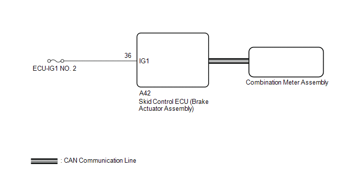
WIRING DIAGRAM
CAUTION / NOTICE / HINT
NOTICE:
- Inspect the fuses for circuits related to this system before performing the following inspection procedure.
- The electric parking brake may still operate up to 20 seconds after the ignition switch is turned off. Before disconnecting connectors or fuses, turn the ignition switch off and wait 20 seconds or more.
- When replacing the skid control ECU (brake actuator assembly), operate the electric parking brake switch assembly as the parking brake indicator light blinks (red) when the ignition switch is first turned to ON.
HINT:
Even if the electric parking brake is operating normally, the parking brake indicator light (red) on the combination meter may be malfunctioning.
PROCEDURE
|
1. |
CHECK CAN COMMUNICATION SYSTEM |
(a) Check if CAN communication system DTCs are output.
Click here
.gif)
|
Result |
Proceed to |
|---|---|
|
DTCs are not output |
A |
|
DTCs are output |
B |
| B | .gif) |
GO TO CAN COMMUNICATION SYSTEM
|
|
.gif)
|
2. |
VEHICLE OPERATION CHECK |
(a) When the vehicle's tires are lifted off the ground and the Techstream is used to operate the electric parking brake, check the condition of the rear tires.
Click here
|
Result |
Proceed to |
|---|---|
|
Lock and release operation is normal and parking brake indicator light turns off or blinks (red) |
A |
|
Lock and release operation is malfunctioning and parking brake indicator light illuminates (red) or turns off according to switch operation |
B |
|
Lock and release operation is malfunctioning and parking brake indicator light turns off or blinks (red) |
C |
| B | |
INSPECT REAR BRAKE |
| C | |
GO TO STEP 5 |
|
|
3. |
PERFORM ACTIVE TEST USING TECHSTREAM (PARKING BRAKE LIGHT) |
(a) Turn the ignition switch off.
(b) Connect the Techstream to the DLC3.
(c) Turn the ignition switch to ON.
(d) Turn the Techstream on.
(e) Enter the following menus: Chassis / Electric Parking Brake / Data List.
(f) Read the Data List according to the display on the Techstream.
Click here
|
Tester Display |
Measurement Item |
Control Range |
Diagnostic Note |
|---|---|---|---|
|
PKB Light |
Parking brake indicator light (red) |
ON or OFF |
|
|
Tester Display |
|---|
|
PKB Light |
(g) Select the Data List on the Techstream.
Click here
|
Tester Display |
Measurement Item |
Range |
Normal Condition |
Diagnostic Note |
|---|---|---|---|---|
|
Parking Brake Light |
Parking brake indicator light (red) output signal |
OFF, Light or Blink |
OFF: Parking brake indicator light (red) turns off Light: Parking brake indicator light (red) illuminates Blink: Parking brake indicator light (red) flashes |
- |
|
Tester Display |
|---|
|
Parking Brake Light |
(h) Check the operating condition of the parking brake indicator light (red) when operating it using the Techstream.
|
Result |
Proceed to |
|---|---|
|
Parking brake indicator light (red) in the Data List does not change using the Active Test. |
A |
|
Parking brake indicator light (red) in the Data List turns ON/OFF using the Active Test. |
B |
| A | |
REPLACE SKID CONTROL ECU (BRAKE ACTUATOR ASSEMBLY) |
|
|
4. |
INSPECT COMBINATION METER ASSEMBLY |
(a) Perform the Active Test of the combination meter assembly using the Techstream.
Click here
|
Tester Display |
|---|
|
Indicat. Park |
(b) Check the combination meter assembly.
OK:
Parking brake indicator light (red) turns on or off in accordance with Techstream operation.
| OK | |
REPLACE SKID CONTROL ECU (BRAKE ACTUATOR ASSEMBLY) |
| NG | |
GO TO METER / GAUGE SYSTEM |
|
5. |
CHECK HARNESS AND CONNECTOR (BATTERY - SKID CONTROL ECU (BRAKE ACTUATOR ASSEMBLY)) |
(a) Turn the ignition switch off.
|
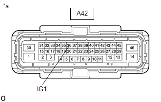
(b) Disconnect the A42 skid control ECU (brake actuator assembly) connector. |
|
(c) Measure the voltage according to the value(s) in the table below.
Standard Voltage:
|
Tester Connection |
Switch Condition |
Specified Condition |
|---|---|---|
|
A42-36 (IG1) - Body ground |
Ignition switch ON |
11 to 14 V |
| OK | |
REPLACE SKID CONTROL ECU (BRAKE ACTUATOR ASSEMBLY) |
| NG | |
REPAIR OR REPLACE HARNESS OR CONNECTOR |
 Open or Short Circuit in Motor (C13A6)
DESCRIPTION
DTC No.
Detection Item
DTC Detection Condition
Trouble Area
Memory
Note
C13A6
Open or Short C ...
 Electric Parking Brake AUTO Indicator Light Circuit
DESCRIPTION
Pulling the electric parking brake switch to the lock side for 5 seconds or more
changes the AUTO function (shift-linked function) to ON, and an AUTO Mode ON message
is displayed on t ...
Other materials:
Toyota CH-R Service Manual > Continuously Variable Transaxle System: Brake ECU Malfunction (P1750)
DESCRIPTION
HINT:
This DTC P1750 is applicable to Mexico models only.
When the ECM receives a malfunction signal from the skid control ECU (brake actuator
assembly), DTC P1750 is stored.
DTC No.
Detection Item
DTC Detection Condition
Trouble Area
...
Toyota CH-R Service Manual > Horn: Horn
Components
COMPONENTS
ILLUSTRATION
*1
LOW PITCHED HORN ASSEMBLY
*2
NO.1 RADIATOR GRILLE RETAINER
*3
NO.1 RADIATOR TO SUPPORT SEAL
-
-
N*m (kgf*cm, ft.*lbf): Specified torque ...
Toyota C-HR (AX20) 2023-2026 Owner's Manual
Toyota CH-R Owners Manual
- For safety and security
- Instrument cluster
- Operation of each component
- Driving
- Interior features
- Maintenance and care
- When trouble arises
- Vehicle specifications
- For owners
Toyota CH-R Service Manual
- Introduction
- Maintenance
- Audio / Video
- Cellular Communication
- Navigation / Multi Info Display
- Park Assist / Monitoring
- Brake (front)
- Brake (rear)
- Brake Control / Dynamic Control Systems
- Brake System (other)
- Parking Brake
- Axle And Differential
- Drive Shaft / Propeller Shaft
- K114 Cvt
- 3zr-fae Battery / Charging
- Networking
- Power Distribution
- Power Assist Systems
- Steering Column
- Steering Gear / Linkage
- Alignment / Handling Diagnosis
- Front Suspension
- Rear Suspension
- Tire / Wheel
- Tire Pressure Monitoring
- Door / Hatch
- Exterior Panels / Trim
- Horn
- Lighting (ext)
- Mirror (ext)
- Window / Glass
- Wiper / Washer
- Door Lock
- Heating / Air Conditioning
- Interior Panels / Trim
- Lighting (int)
- Meter / Gauge / Display
- Mirror (int)
- Power Outlets (int)
- Pre-collision
- Seat
- Seat Belt
- Supplemental Restraint Systems
- Theft Deterrent / Keyless Entry

0.0101