Toyota CH-R Service Manual: Test Mode Procedure
TEST MODE PROCEDURE
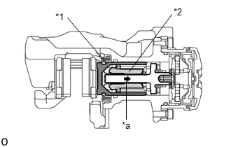
REAR BRAKE PAD REPLACEMENT MODE
|
*1 |
Rear Disc Brake Piston |
|
*2 |
Nut |
|
*a |
The nut moves inward in pad replacement mode |
HINT:
When replacing the rear disc brake pad and rear disc, since the nut inside the rear disc brake cylinder assembly is in an advanced position, it is necessary to move the nut back inside the cylinder. The nut can be moved back using pad replacement mode.
(a) Pad replacement mode
- Turn the ignition switch off.
- Connect the Techstream to the DLC3.
- Turn the ignition switch to ON.
- Turn the Techstream on.
- Enter the following menus: Chassis / ABS/VSC/TRAC/EPB / Utility / Check Mode
- Follow the Techstream display and select "Next".
- Push and hold the electric parking brake switch (electric parking brake
switch assembly) to the release side for 5 seconds or more.
NOTICE:
- Make sure to perform this procedure with the ignition switch to ON.
- Make sure that the brake pedal is not depressed when performing this procedure.
- When the system changes to pad replacement mode, DTC C13A7/43 may be stored. If the DTC is stored, clear the DTCs after the procedure (rear brake pad replacement, etc.) is complete.
HINT:
The parking brake indicator light flashes (red) (0.25 second intervals). After a short time, the parking brake actuator assembly operates (if the parking brake is engaged, the motor will operate to disengage the parking brake, and then will operate again). Once the parking brake actuator assembly is in the pad replacement position, the parking brake indicator light flashes (red) (1 second intervals).
|
Tester Display |
|---|
|
Check Mode |
- Turn the ignition switch off.
- Turn the ignition switch to ON.
- Within 8 seconds, operate the electric parking brake switch (electric
parking brake switch assembly) to perform 3 lock side ON operations (from
off (release) to on (pull)) and then 3 release side ON operations (from
off (release) to on (push)).
NOTICE:
- If the operation is performed too quickly, the system may not respond. If the system does not respond, perform the operation again at a slower speed.
- The parking brake must be released.
HINT:
The parking brake indicator light (red) flashes (0.25 second intervals).
- Push and hold the electric parking brake switch (electric parking brake
switch assembly) to the release side for 5 seconds or more.
NOTICE:
- Make sure to perform this procedure with the ignition switch to ON.
- Make sure that the brake pedal is not depressed when performing this procedure.
- When the system changes to pad replacement mode, DTC C13A7 may be stored. If the DTC is stored, clear the DTCs after the procedure (rear brake pad replacement, etc.) is complete.
HINT:
After a short time passes, the parking brake actuator assembly operates (if operated from the parking brake locked condition, the motor of the parking brake actuator assembly is temporarily stopped after being operated, and then operation starts again), and once the assembly finishes operating, the parking brake indicator light (red) flashes slowly (1 second intervals). (Nut moves back inside the cylinder and system enters pad replacement mode).
(b) Turn the ignition switch off.
NOTICE:
Do not operate the electric parking brake switch (electric parking brake switch assembly) until the procedure is complete. If operated, the system will return to its normal condition.
- Disconnect the Techstream from the DLC3.
(c) Normal condition recovery
(1) After the procedure (rear brake pad replacement, etc.) is complete, turn the ignition switch ON and pull the electric parking brake switch (electric parking brake switch assembly) to the lock side for 5 seconds or more.
NOTICE:
- When performing work (replacing the rear brake pad, etc.), do not operate the electric parking brake switch (electric parking brake switch assembly) or turn the ignition switch to ON and operate the shift lever. If the electric parking brake switch (electric parking brake switch assembly) or shift lever is operated, the parking brake may operate and the rear disc brake piston may fall off. Also, make sure to disconnect the connector of the parking brake actuator assembly or disconnect the cable from the negative (-) battery terminal.
- When DTC C13A7 is stored, clear the DTCs.
 How To Proceed With Troubleshooting
CAUTION / NOTICE / HINT
HINT:
*: Use the Techstream.
PROCEDURE
1.
VEHICLE BROUGHT TO WORKSHOP
NEXT
...
 Problem Symptoms Table
PROBLEM SYMPTOMS TABLE
HINT:
Use the table below to help determine the cause of problem symptoms.
If multiple suspected areas are listed, the potential causes of the symptoms
are lis ...
Other materials:
Toyota CH-R Service Manual > Power Steering System: Lost Communication With ECM/PCM "A" (U0100,U0129,U023A)
DESCRIPTION
The power steering ECU assembly receives signals from the ECM and skid control
ECU (brake actuator assembly) via CAN communication.
DTC No.
Detection Item
DTC Detection Condition
Trouble Area
Warning Indicate
Return-to ...
Toyota CH-R Service Manual > Can Communication System: Open in One Side of Bus 3 Branch Line
DESCRIPTION
When the CAN bus main lines are normal (no open, short to ground, short to +B
or short between lines) and there is an ECU or sensor on the "Communication Bus
Check" screen that is indicated as not communicating or whose connection status
on the "Communication Bus Ch ...
Toyota C-HR (AX20) 2023-2026 Owner's Manual
Toyota CH-R Owners Manual
- For safety and security
- Instrument cluster
- Operation of each component
- Driving
- Interior features
- Maintenance and care
- When trouble arises
- Vehicle specifications
- For owners
Toyota CH-R Service Manual
- Introduction
- Maintenance
- Audio / Video
- Cellular Communication
- Navigation / Multi Info Display
- Park Assist / Monitoring
- Brake (front)
- Brake (rear)
- Brake Control / Dynamic Control Systems
- Brake System (other)
- Parking Brake
- Axle And Differential
- Drive Shaft / Propeller Shaft
- K114 Cvt
- 3zr-fae Battery / Charging
- Networking
- Power Distribution
- Power Assist Systems
- Steering Column
- Steering Gear / Linkage
- Alignment / Handling Diagnosis
- Front Suspension
- Rear Suspension
- Tire / Wheel
- Tire Pressure Monitoring
- Door / Hatch
- Exterior Panels / Trim
- Horn
- Lighting (ext)
- Mirror (ext)
- Window / Glass
- Wiper / Washer
- Door Lock
- Heating / Air Conditioning
- Interior Panels / Trim
- Lighting (int)
- Meter / Gauge / Display
- Mirror (int)
- Power Outlets (int)
- Pre-collision
- Seat
- Seat Belt
- Supplemental Restraint Systems
- Theft Deterrent / Keyless Entry

0.0088