Toyota CH-R Service Manual: System Description
SYSTEM DESCRIPTION
OUTLINE OF THEFT DETERRENT SYSTEM
- The theft deterrent system can be set by locking the doors using any
of the following operations:
- Entry lock operation*1
- Wireless lock operation
- *1: w/ Smart Key System
- In the armed state, the alarm function will be activated if one of the
following conditions is met:
- Any of the doors is unlocked.
- Any of the doors or the hood is opened.
- In the alarm sounding state, the system blinks the turn signal lights. At the same time, the system sounds the vehicle horns and security horn assembly to deter break-in and theft as well as to warn people around the vehicle.
- The theft deterrent system can be canceled by unlocking the doors using
any of the following operations:
- Entry lock operation*1
- Wireless lock operation
- Key linked lock operation*2
- *1: w/ Smart Key System
- *2: This function is set through the customize function.
Click here
.gif)
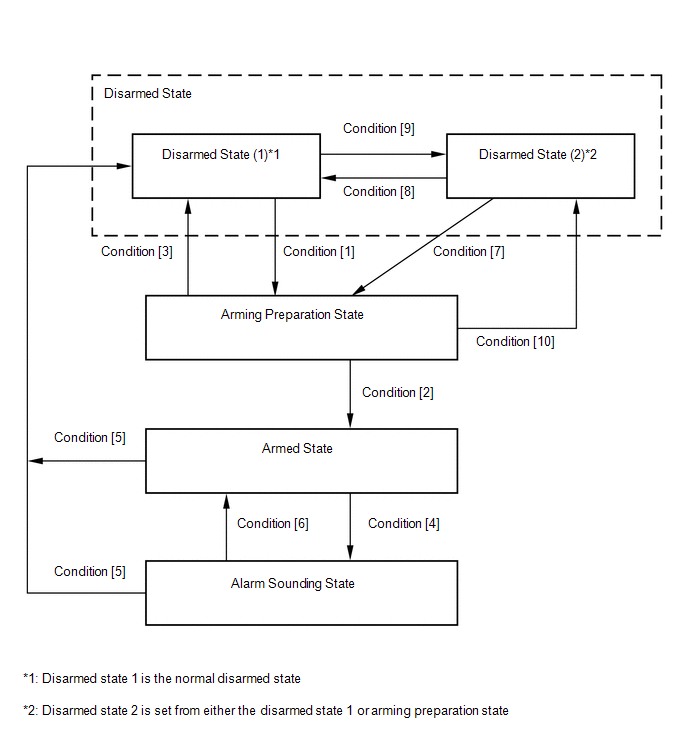
- The theft deterrent system has an active arming mode. There are 4 states in this mode; a disarmed state, an arming preparation state, an armed state and an alarm sounding state.
(a) Disarmed state:
- The alarm function is not operating.
- The theft deterrent system is not operating.
(b) Arming preparation state:
- The time until the system goes into the armed state.
- The theft deterrent system is not operating.
(c) Armed state:
- The theft deterrent system is operating.
(d) Alarm sounding state:
- The alarm function is operating.
Alarm time:
Approximately 27.5 seconds
Alarm Methods|
Alarm Method |
Turn Signal Lights |
Blinking |
|
Vehicle Horns |
Sounding (Approximately 0.4-second cycles) |
|
|
Security Horn Assembly |
Sounding (Approximately 0.4-second cycles) |
FUNCTION OF MAIN COMPONENTS
|
Component |
Function |
|---|---|
|
Security indicator light |
Informs driver of theft deterrent system status. |
|
Security horn assembly |
Sounds when attempted break-in or theft is detected. |
|
Turn signal lights |
Blink when attempted break-in or theft is detected. |
|
Vehicle horns |
Sound when attempted break-in or theft is detected. |
|
Detects door status (open or closed). |
|
Door unlock detection switch |
Detects door status (locked or unlocked). |
|
Hood courtesy switch (Hood lock assembly) |
Detects hood status (open or closed). |
|
Certification ECU (Smart key ECU assembly)*1 |
|
|
Main body ECU (multiplex network body ECU)*2 |
Receives wireless door lock/unlock signal. |
- *1: w/ Smart Key System
- *2: w/o Smart Key System
ACTIVE ARMING MODE
(a) Active arming mode:
This system operates as described in the diagram below when one of the items for each condition is met.
HINT:
The term "all doors" used in this section refers to the driver door, front passenger door, rear door LH, rear door RH and back door.
 w/ Smart Key System
|
Condition |
Item |
|---|---|
|
Condition [1] |
In disarmed state 1, when the engine switch is turned off, the system state is changed if the following condition is met:
|
|
Condition [2] |
|
|
Condition [3] |
|
|
Condition [4] |
|
|
Condition [5] |
|
|
Condition [6] |
|
|
Condition [7] |
|
|
Condition [8] |
|
|
Condition [9] |
In disarmed state 1, when the engine switch is turned off, the system state is changed if the following condition is met:
|
|
Condition [10] |
|
|
Condition |
Item |
|---|---|
|
Condition [1] |
In disarmed state 1, when the ignition switch is off, the system state is changed if the following condition is met when the key is not in the key cylinder:
|
|
Condition [2] |
|
|
Condition [3] |
|
|
Condition [4] |
|
|
Condition [5] |
|
|
Condition [6] |
|
|
Condition [7] |
|
|
Condition [8] |
|
|
Condition [9] |
In disarmed state 1, when the ignition switch is off, the system state is changed if the following condition is met when the key is not in the key cylinder:
|
|
Condition [10] |
|
FORCED DOOR LOCK CONTROL
(a) The forced door lock control prevents the vehicle from being tampered with. Immediately after a door is unlocked (armed state), all doors are forced to lock by a forced door lock signal.
(1) If the following conditions are met, the forced door lock control is operated.
- The theft deterrent system is in the armed state.
- Any door is unlocked.
SECURITY INDICATOR LIGHT OUTPUT
(a) According to the state of the theft deterrent system, the main body ECU (multiplex network body ECU) outputs a signal to turn the security indicator light on. However, some of the actual lighting conditions of the security indicator light are different from the output signals of the main body ECU (multiplex network body ECU).
Output|
State of Theft Deterrent System |
Security Indicator Light |
|
|---|---|---|
|
Output Signal from Main Body ECU (Multiplex Network Body ECU) |
Actual Lighting Condition |
|
|
Disarmed state (1), (2) |
Off |
|
|
Arming preparation state |
On |
On |
|
Armed state |
Off |
Blinking |
|
Alarm sounding state |
On |
On |
|
Time |
Security Indicator Light |
|---|---|
|
0.125 sec. |
On |
|
1.875 sec. |
Off |
HINT:
When the immobiliser system is set, the security indicator light blinks during both the disarmed state and the armed state due to output signals from the immobiliser system.
 Parts Location
PARTS LOCATION
ILLUSTRATION
*1
HOOD COURTESY SWITCH
*2
LOW PITCHED HORN ASSEMBLY
*3
HORN RELAY
*4
SECU ...
 System Diagram
SYSTEM DIAGRAM
...
Other materials:
Toyota CH-R Service Manual > Air Conditioning System(for Automatic Air Conditioning System With Side-mounted
Air Conditioner Pressure Sensor): Compressor Solenoid Circuit (B1451)
DESCRIPTION
In this circuit, the cooler compressor assembly (compressor solenoid) receives
a refrigerant compression demand signal from the air conditioning amplifier assembly.
Based on this signal, the cooler compressor assembly (compressor solenoid) changes
the amount of compressor output.
...
Toyota CH-R Owners Manual > Adjusting the steering wheel and mirrors: Inside rear view mirror
The rear view mirror's position can be adjusted to enable sufficient
confirmation of the rear view.
Adjusting the height of rear view mirror
The height of the rear view mirror can be adjusted to suit your driving posture.
Adjust the height of the rear view mirror by moving it up and down.
...
Toyota C-HR (AX20) 2023-2026 Owner's Manual
Toyota CH-R Owners Manual
- For safety and security
- Instrument cluster
- Operation of each component
- Driving
- Interior features
- Maintenance and care
- When trouble arises
- Vehicle specifications
- For owners
Toyota CH-R Service Manual
- Introduction
- Maintenance
- Audio / Video
- Cellular Communication
- Navigation / Multi Info Display
- Park Assist / Monitoring
- Brake (front)
- Brake (rear)
- Brake Control / Dynamic Control Systems
- Brake System (other)
- Parking Brake
- Axle And Differential
- Drive Shaft / Propeller Shaft
- K114 Cvt
- 3zr-fae Battery / Charging
- Networking
- Power Distribution
- Power Assist Systems
- Steering Column
- Steering Gear / Linkage
- Alignment / Handling Diagnosis
- Front Suspension
- Rear Suspension
- Tire / Wheel
- Tire Pressure Monitoring
- Door / Hatch
- Exterior Panels / Trim
- Horn
- Lighting (ext)
- Mirror (ext)
- Window / Glass
- Wiper / Washer
- Door Lock
- Heating / Air Conditioning
- Interior Panels / Trim
- Lighting (int)
- Meter / Gauge / Display
- Mirror (int)
- Power Outlets (int)
- Pre-collision
- Seat
- Seat Belt
- Supplemental Restraint Systems
- Theft Deterrent / Keyless Entry

0.0125