Toyota CH-R Service Manual: Reverse Signal Circuit
DESCRIPTION
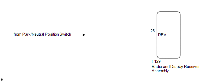
The radio and display receiver assembly receives a reverse signal from the park/neutral position switch.
WIRING DIAGRAM
PROCEDURE
|
1. |
CHECK BACK-UP LIGHT |
(a) Move the shift lever to R and check if the back-up lights come on.
OK:
The back-up lights come on.
| NG | .gif) |
GO TO LIGHTING SYSTEM (for Exterior) |
|
.gif)
|
2. |
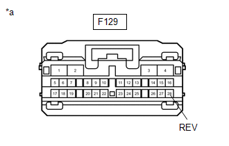
CHECK HARNESS AND CONNECTOR (REVERSE SIGNAL) |
(a) Disconnect the radio and display receiver assembly connector.
|
(b) Measure the voltage according to the value(s) in the table below. Standard Voltage:
|
|
| OK | |
PROCEED TO NEXT SUSPECTED AREA SHOWN IN PROBLEM SYMPTOMS TABLE |
| NG | |
REPAIR OR REPLACE HARNESS OR CONNECTOR |
 Mute Signal Circuit between Radio Receiver and Telematics Transceiver
DESCRIPTION
The telematics transceiver sends a mute signal to the radio and display receiver
assembly.
The radio and display receiver assembly controls the volume according to the
mute signal fr ...
 Microphone Circuit
DESCRIPTION
w/o Manual (SOS) Switch:
The radio and display receiver assembly, map light assembly and telephone
microphone assembly are connected to each other using the microphone conne ...
Other materials:
Toyota CH-R Service Manual > Smart Key System(for Entry Function): Diagnostic Trouble Code Chart
DIAGNOSTIC TROUBLE CODE CHART
Smart Key System (for Entry Function)
DTC No.
Detection Item
Link
B27A1
Open in Driver Side Electrical Antenna Circuit
B27A2
Open in Front Passenger Side Electrical A ...
Toyota CH-R Service Manual > Instrument Panel Safety Pad: Installation
INSTALLATION
PROCEDURE
1. INSTALL INSTRUMENT PANEL SAFETY PAD SUB-ASSEMBLY
(a) Engage the guides to install the instrument panel safety pad sub-assembly
as shown in the illustration.
Install in this Direction (1)
Install in this Direction (2)
...
Toyota C-HR (AX20) 2023-2026 Owner's Manual
Toyota CH-R Owners Manual
- For safety and security
- Instrument cluster
- Operation of each component
- Driving
- Interior features
- Maintenance and care
- When trouble arises
- Vehicle specifications
- For owners
Toyota CH-R Service Manual
- Introduction
- Maintenance
- Audio / Video
- Cellular Communication
- Navigation / Multi Info Display
- Park Assist / Monitoring
- Brake (front)
- Brake (rear)
- Brake Control / Dynamic Control Systems
- Brake System (other)
- Parking Brake
- Axle And Differential
- Drive Shaft / Propeller Shaft
- K114 Cvt
- 3zr-fae Battery / Charging
- Networking
- Power Distribution
- Power Assist Systems
- Steering Column
- Steering Gear / Linkage
- Alignment / Handling Diagnosis
- Front Suspension
- Rear Suspension
- Tire / Wheel
- Tire Pressure Monitoring
- Door / Hatch
- Exterior Panels / Trim
- Horn
- Lighting (ext)
- Mirror (ext)
- Window / Glass
- Wiper / Washer
- Door Lock
- Heating / Air Conditioning
- Interior Panels / Trim
- Lighting (int)
- Meter / Gauge / Display
- Mirror (int)
- Power Outlets (int)
- Pre-collision
- Seat
- Seat Belt
- Supplemental Restraint Systems
- Theft Deterrent / Keyless Entry

0.0103