Toyota CH-R Service Manual: Mute Signal Circuit between Radio Receiver and Telematics Transceiver
DESCRIPTION
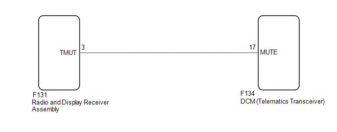
The telematics transceiver sends a mute signal to the radio and display receiver assembly.
The radio and display receiver assembly controls the volume according to the mute signal from the telematics transceiver.
WIRING DIAGRAM
CAUTION / NOTICE / HINT
NOTICE:
Depending on the parts that are replaced during vehicle inspection or maintenance, performing initialization, registration or calibration may be needed. Refer to Precaution for Audio and Visual System.
Click here
.gif)
PROCEDURE
|
1. |
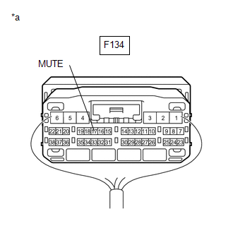
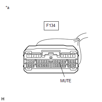
INSPECT DCM (TELEMATICS TRANSCEIVER) |
|
(a) Measure the voltage according to the value(s) in the table below. Standard Voltage:
|
|
| OK | .gif) |
PROCEED TO NEXT SUSPECTED AREA SHOWN IN PROBLEM SYMPTOMS TABLE |
|
.gif)
|
2. |
CHECK HARNESS AND CONNECTOR (RADIO AND DISPLAY RECEIVER ASSEMBLY - DCM (TELEMATICS TRANSCEIVER)) |
(a) Disconnect the F131 radio and display receiver assembly connector.
(b) Disconnect the F134 DCM (telematics transceiver) connector.
(c) Measure the resistance according to the value(s) in the table below.
Standard Resistance:
|
Tester Connection |
Condition |
Specified Condition |
|---|---|---|
|
F131-3 (TMUT) - F134-17 (MUTE) |
Always |
Below 1 Ω |
|
F131-3 (TMUT) or F134-17 (MUTE) - Body ground |
Always |
10 kΩ or higher |
| NG | |
REPAIR OR REPLACE HARNESS OR CONNECTOR |
|
|
3. |
INSPECT RADIO AND DISPLAY RECEIVER ASSEMBLY |
(a) Disconnect the DCM (telematics transceiver) connector.
|
(b) Measure the voltage according to the value(s) in the table below. Standard Voltage:
|
|
| OK | |
REPLACE DCM (TELEMATICS TRANSCEIVER) |
| NG | |
REPLACE RADIO AND DISPLAY RECEIVER ASSEMBLY |
 Data Signal Circuit between Radio Receiver and Stereo Jack Adapter
DESCRIPTION
The No. 1 stereo jack adapter assembly sends the sound data signal or image data
signal from a USB device to the radio and display receiver assembly via this circuit.
WIRING DIAGRAM
...
 Reverse Signal Circuit
DESCRIPTION
The radio and display receiver assembly receives a reverse signal from the park/neutral
position switch.
WIRING DIAGRAM
PROCEDURE
1.
CHECK BACK-UP LIGHT
...
Other materials:
Toyota CH-R Service Manual > Door Lock: Transmitter Battery(w/o Smart Key System)
Components
COMPONENTS
ILLUSTRATION
*1
TRANSMITTER BATTERY
*2
TRANSMITTER HOUSING COVER
*3
DOOR CONTROL TRANSMITTER PACKING
*4
TRANSMITTER HOUSING CASE
...
Toyota CH-R Owners Manual > Steps to take in an emergency: Fuel pump shut off system
To minimize the risk of fuel leakage when the engine stalls or when
an airbag inflates upon collision, the fuel pump shut off system stops the supply
of fuel to the engine.
Follow the procedure below to restart the engine after the system is activated.
Vehicles without a smart key system
1. T ...
Toyota C-HR (AX20) 2023-2026 Owner's Manual
Toyota CH-R Owners Manual
- For safety and security
- Instrument cluster
- Operation of each component
- Driving
- Interior features
- Maintenance and care
- When trouble arises
- Vehicle specifications
- For owners
Toyota CH-R Service Manual
- Introduction
- Maintenance
- Audio / Video
- Cellular Communication
- Navigation / Multi Info Display
- Park Assist / Monitoring
- Brake (front)
- Brake (rear)
- Brake Control / Dynamic Control Systems
- Brake System (other)
- Parking Brake
- Axle And Differential
- Drive Shaft / Propeller Shaft
- K114 Cvt
- 3zr-fae Battery / Charging
- Networking
- Power Distribution
- Power Assist Systems
- Steering Column
- Steering Gear / Linkage
- Alignment / Handling Diagnosis
- Front Suspension
- Rear Suspension
- Tire / Wheel
- Tire Pressure Monitoring
- Door / Hatch
- Exterior Panels / Trim
- Horn
- Lighting (ext)
- Mirror (ext)
- Window / Glass
- Wiper / Washer
- Door Lock
- Heating / Air Conditioning
- Interior Panels / Trim
- Lighting (int)
- Meter / Gauge / Display
- Mirror (int)
- Power Outlets (int)
- Pre-collision
- Seat
- Seat Belt
- Supplemental Restraint Systems
- Theft Deterrent / Keyless Entry

0.0099