Toyota CH-R Service Manual: Microphone Circuit
DESCRIPTION
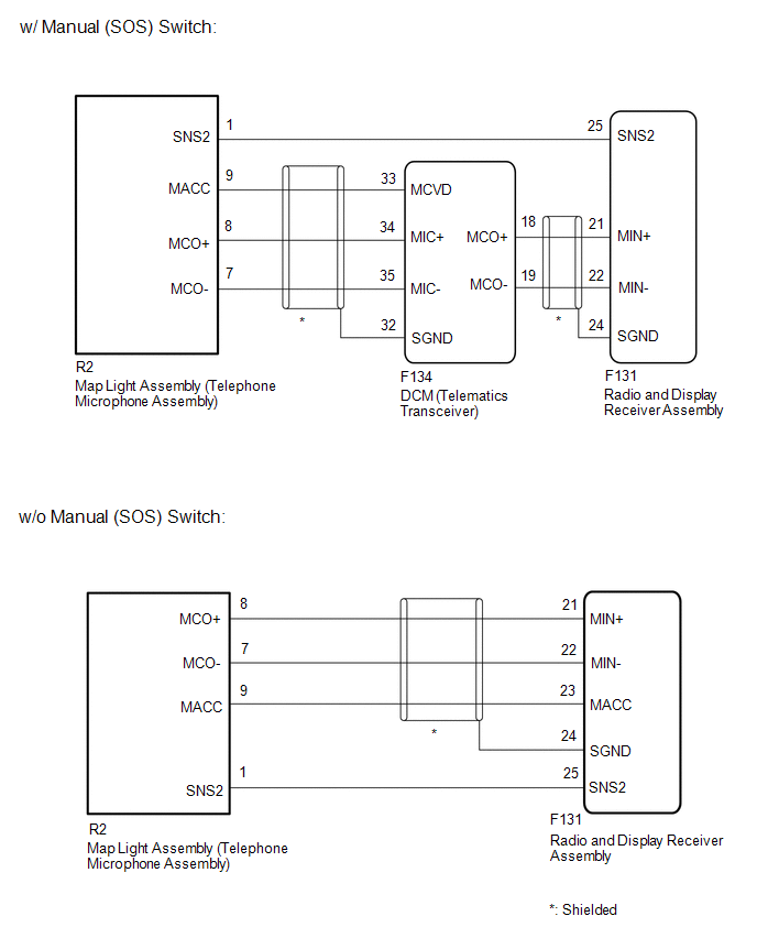
- w/o Manual (SOS) Switch:
The radio and display receiver assembly, map light assembly and telephone microphone assembly are connected to each other using the microphone connection detection signal lines.
Using this circuit, the radio and display receiver assembly sends power to the map light assembly and telephone microphone assembly, and the map light assembly and telephone microphone assembly sends microphone signals to the radio and display receiver assembly.
- w/ Manual (SOS) Switch:
The radio and display receiver assembly, map light assembly and telephone microphone assembly are connected to each other using the microphone connection detection signal lines.
Using this circuit, the DCM (telematics transceiver) sends power to the map light assembly and telephone microphone assembly, and the map light assembly and telephone microphone assembly sends microphone signals to the radio and display receiver assembly via the DCM (telematics transceiver).
WIRING DIAGRAM
CAUTION / NOTICE / HINT
NOTICE:
- Depending on the parts that are replaced during vehicle inspection or
maintenance, performing initialization, registration or calibration may
be needed. Refer to Precaution for Audio and Visual System.
Click here
.gif)
- When replacing the radio and display receiver assembly, always replace
it with a new one. If a radio and display receiver assembly which was installed
to another vehicle is used, the following may occur:
- A communication malfunction DTC is stored.
- The radio and display receiver assembly may not operate normally.
PROCEDURE
|
1. |
CHECK MICROPHONE AND VOICE RECOGNITION (INPUT TO RADIO AND DISPLAY RECEIVER ASSEMBLY) |
|
(a) Enter the "Microphone Check" screen. Refer to Check Microphone (Input to radio and display receiver assembly) in Operation Check. Click here
|
|
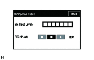
(b) When voice is input into the microphone, check that the microphone input level meter changes according to the input voice.
OK:
Check result is normal.
|
Result |
Proceed to |
|---|---|
|
NG (w/ Manual (SOS) Switch) |
A |
|
NG (w/o Manual (SOS) Switch) |
B |
|
OK |
C |
| A | .gif) |
GO TO STEP 10 |
| C | |
USE SIMULATION METHOD TO CHECK |
|
.gif)
|
2. |
CHECK HARNESS AND CONNECTOR (RADIO AND DISPLAY RECEIVER ASSEMBLY - MAP LIGHT ASSEMBLY (TELEPHONE MICROPHONE ASSEMBLY)) |
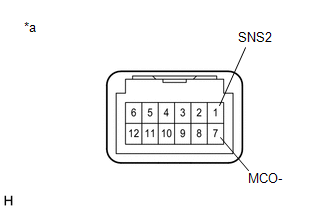
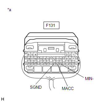
(a) Disconnect the F131 radio and display receiver assembly connector.
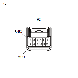
(b) Disconnect the R2 map light assembly (telephone microphone assembly) connector.
(c) Measure the resistance according to the value(s) in the table below.
Standard Resistance:
|
Tester Connection |
Condition |
Specified Condition |
|---|---|---|
|
F131-25 (SNS2) - R2-1 (SNS2) |
Always |
Below 1 Ω |
|
F131-25 (SNS2) or R2-1 (SNS2) - Body ground |
Always |
10 kΩ or higher |
| NG | |
REPAIR OR REPLACE HARNESS OR CONNECTOR |
|
|
3. |
CHECK HARNESS AND CONNECTOR (RADIO AND DISPLAY RECEIVER ASSEMBLY - DCM (TELEMATICS TRANSCEIVER)) |
(a) Disconnect the F131 radio and display receiver assembly connector.
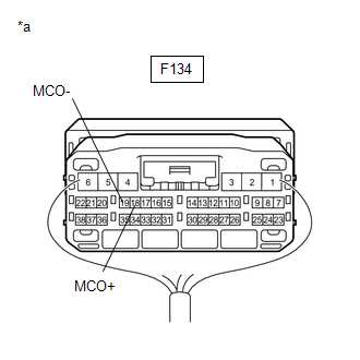
(b) Disconnect the F134 DCM (telematics transceiver) connector.
(c) Measure the resistance according to the value(s) in the table below.
Standard Resistance:
|
Tester Connection |
Condition |
Specified Condition |
|---|---|---|
|
F131-21 (MIN+) - F134-18 (MCO+) |
Always |
Below 1 Ω |
|
F131-22 (MIN-) - F134-19 (MCO-) |
Always |
Below 1 Ω |
|
F131-21 (MIN+) or F134-18 (MCO+) - Body ground |
Always |
10 kΩ or higher |
|
F131-22 (MIN-) or F134-19 (MCO-) - Body ground |
Always |
10 kΩ or higher |
|
F131-24 (SGND) - Body ground |
Always |
10 kΩ or higher |
| NG | |
REPAIR OR REPLACE HARNESS OR CONNECTOR |
|
|
4. |
CHECK HARNESS AND CONNECTOR (DCM (TELEMATICS TRANSCEIVER) - MAP LIGHT ASSEMBLY) |
(a) Disconnect the F134 DCM (telematics transceiver) connector.
(b) Disconnect the R2 map light assembly connector.
(c) Measure the resistance according to the value(s) in the table below.
Standard Resistance:
|
Tester Connection |
Condition |
Specified Condition |
|---|---|---|
|
F134-33 (MCVD) - R2-9 (MACC) |
Always |
Below 1 Ω |
|
F134-34 (MIC+) - R2-8 (MCO+) |
Always |
Below 1 Ω |
|
F134-35 (MIC-) - R2-7 (MCO-) |
Always |
Below 1 Ω |
|
F134-33 (MCVD) or R2-9 (MACC) - Body ground |
Always |
10 kΩ or higher |
|
F134-34 (MIC+) or R2-8 (MCO+) - Body ground |
Always |
10 kΩ or higher |
|
F134-35 (MIC-) or R2-7 (MCO-) - Body ground |
Always |
10 kΩ or higher |
|
F134-32 (SGND) - Body ground |
Always |
10 kΩ or higher |
| NG | |
REPAIR OR REPLACE HARNESS OR CONNECTOR |
|
|
5. |
INSPECT RADIO AND DISPLAY RECEIVER ASSEMBLY |
|
(a) Connect the radio and display receiver assembly connector. |
|
(b) Disconnect the F134 DCM (telematics transceiver) connector.
(c) Measure the resistance according to the value(s) in the table below.
Standard Resistance:
|
Tester Connection |
Condition |
Specified Condition |
|---|---|---|
|
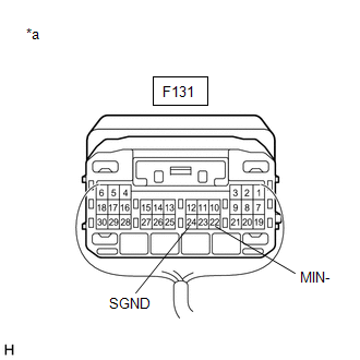
F131-24 (SGND) - Body ground |
Always |
Below 1 Ω |
|
F131-22 (MIN-) - Body ground |
Always |
Below 1 Ω |
| NG | |
REPLACE RADIO AND DISPLAY RECEIVER ASSEMBLY |
|
|
6. |
INSPECT DCM (TELEMATICS TRANSCEIVER) |
(a) Connect the DCM (telematics transceiver) connector.
|
(b) Measure the voltage according to the value(s) in the table below. Standard Voltage:
|
|
(c) Measure the resistance according to the value(s) in the table below.
Standard Resistance:
|
Tester Connection |
Condition |
Specified Condition |
|---|---|---|
|
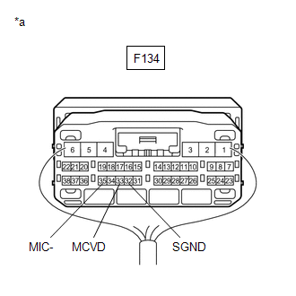
F134-35 (MIC-) - Body ground |
Always |
Below 1 Ω |
|
F134-32 (SGND) - Body ground |
Always |
Below 1 Ω |
| NG | |
REPLACE DCM (TELEMATICS TRANSCEIVER) |
|
|
7. |
INSPECT MAP LIGHT ASSEMBLY (TELEPHONE MICROPHONE ASSEMBLY) |
(a) Remove the map light assembly (telephone microphone assembly).
Click here
|
(b) Measure the resistance according to the value(s) in the table below. Standard Resistance:
|
|
| NG | |
REPLACE MAP LIGHT ASSEMBLY (TELEPHONE MICROPHONE ASSEMBLY) |
|
|
8. |
INSPECT MAP LIGHT ASSEMBLY (TELEPHONE MICROPHONE ASSEMBLY) (OUTPUT TO DCM (TELEMATICS TRANSCEIVER)) |
(a) Connect the F131 radio and display receiver assembly connector.
(b) Connect the R2 map light assembly (telephone microphone assembly) connector.
(c) Connect the R134 DCM (telematics transceiver) connector.
(d) Turn the ignition switch ACC.
|
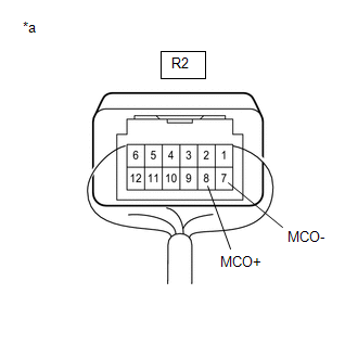
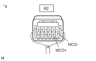
(e) Connect an oscilloscope to terminals 8 (MCO+) and 7 (MCO-) of the R2 map light assembly (telephone microphone assembly) connector. |
|
|
Result |
Proceed to |
|---|---|
|
A waveform synchronized with the voice input to the map light assembly (telephone microphone assembly) is output. |
A |
|
A waveform synchronized with the voice input to the map light assembly (telephone microphone assembly) is not output. |
B |
| B | |
REPLACE MAP LIGHT ASSEMBLY (TELEPHONE MICROPHONE ASSEMBLY) |
|
|
9. |
INSPECT DCM (TELEMATICS TRANSCEIVER) (OUTPUT TO RADIO AND DISPLAY RECEIVER ASSEMBLY) |
(a) Connect the F131 radio and display receiver assembly connector.
(b) Connect the R2 map light assembly (telephone microphone assembly) connector.
(c) Connect the F134 DCM (telematics transceiver) connector.
(d) Turn the ignition switch ACC.
|
(e) Connect an oscilloscope to terminals 18 (MCO+) and 19 (MCO-) of the F134 DCM (telematics transceiver) connector. |
|
|
Result |
Proceed to |
|---|---|
|
A waveform synchronized with the voice input to the map light assembly (telephone microphone assembly) is output. |
A |
|
A waveform synchronized with the voice input to the map light assembly (telephone microphone assembly) is not output. |
B |
| A | |
PROCEED TO NEXT SUSPECTED AREA SHOWN IN PROBLEM SYMPTOMS TABLE |
| B | |
REPLACE DCM (TELEMATICS TRANSCEIVER) |
|
10. |
CHECK HARNESS AND CONNECTOR (RADIO AND DISPLAY RECEIVER ASSEMBLY - MAP LIGHT ASSEMBLY (TELEPHONE MICROPHONE ASSEMBLY)) |
(a) Disconnect the F131 radio and display receiver assembly connector.
(b) Disconnect the R2 map light assembly (telephone microphone assembly) connector.
(c) Measure the resistance according to the value(s) in the table below.
Standard Resistance:
|
Tester Connection |
Condition |
Specified Condition |
|---|---|---|
|
F131-25 (SNS2) - R2-1 (SNS2) |
Always |
Below 1 Ω |
|
F131-23 (MACC) - R2-9 (MACC) |
Always |
Below 1 Ω |
|
F131-21 (MIN+) - R2-8 (MCO+) |
Always |
Below 1 Ω |
|
F131-22 (MIN-) - R2-7 (MCO-) |
Always |
Below 1 Ω |
|
F131-25 (SNS2) or R2-1 (SNS2) - Body ground |
Always |
10 kΩ or higher |
|
F131-23 (MACC) or R2-9 (MACC) - Body ground |
Always |
10 kΩ or higher |
|
F131-21 (MIN+) or R2-8 (MCO+) - Body ground |
Always |
10 kΩ or higher |
|
F131-22 (MIN-) or R2-7 (MCO-) - Body ground |
Always |
10 kΩ or higher |
|
F131-24 (SGND) - Body ground |
Always |
10 kΩ or higher |
| NG | |
REPAIR OR REPLACE HARNESS OR CONNECTOR |
|
|
11. |
INSPECT RADIO AND DISPLAY RECEIVER ASSEMBLY |
(a) Connect the F131 radio and display receiver assembly connector.
(b) Connect the R2 map light assembly (telephone microphone assembly) connector.
|
(c) Measure the voltage according to the value(s) in the table below. Standard Voltage:
|
|
(d) Measure the resistance according to the value(s) in the table below.
Standard Resistance:
|
Tester Connection |
Condition |
Specified Condition |
|---|---|---|
|
F131-24 (SGND) - Body ground |
Always |
Below 1 Ω |
|
F131-22 (MIN-) - Body ground |
Always |
Below 1 Ω |
| NG | |
REPLACE RADIO AND DISPLAY RECEIVER ASSEMBLY |
|
|
12. |
INSPECT MAP LIGHT ASSEMBLY (TELEPHONE MICROPHONE ASSEMBLY) |
(a) Remove the map light assembly (telephone microphone assembly).
Click here
|
(b) Measure the resistance according to the value(s) in the table below. Standard Resistance:
|
|
| NG | |
REPLACE MAP LIGHT ASSEMBLY (TELEPHONE MICROPHONE ASSEMBLY) |
|
|
13. |
INSPECT MAP LIGHT ASSEMBLY (TELEPHONE MICROPHONE ASSEMBLY) |
(a) Connect the F131 radio and display receiver assembly connector.
(b) Connect the R2 map light assembly (telephone microphone assembly) connector.
(c) Turn the ignition switch on (ACC).
|
(d) Connect an oscilloscope to terminals 8 (MCO+) and 7 (MCO-) of the R2 map light assembly (telephone microphone assembly) connector. |
|
|
Result |
Proceed to |
|---|---|
|
A waveform synchronized with the voice input to the map light assembly (telephone microphone assembly) is output. |
A |
|
A waveform synchronized with the voice input to the map light assembly (telephone microphone assembly) is not output. |
B |
| A | |
PROCEED TO NEXT SUSPECTED AREA SHOWN IN PROBLEM SYMPTOMS TABLE |
| B | |
REPLACE MAP LIGHT ASSEMBLY (TELEPHONE MICROPHONE ASSEMBLY) |
 Reverse Signal Circuit
DESCRIPTION
The radio and display receiver assembly receives a reverse signal from the park/neutral
position switch.
WIRING DIAGRAM
PROCEDURE
1.
CHECK BACK-UP LIGHT
...
 Radio Receiver Power Source Circuit
DESCRIPTION
This is the power source circuit to operate the radio and display receiver assembly.
WIRING DIAGRAM
CAUTION / NOTICE / HINT
NOTICE:
Inspect the fuses for circuits related to this sy ...
Other materials:
Toyota CH-R Service Manual > Back Door Outside Garnish: Disassembly
DISASSEMBLY
PROCEDURE
1. REMOVE NO. 2 BACK DOOR OUTSIDE GARNISH
(a) Remove the 7 No. 1 outside moulding retainers and No. 2 back door outside
garnish as shown in the illustration.
Remove in this Direction
2. REMOVE BACK DOOR GARNISH SIDE PROTECTOR LH
...
Toyota CH-R Service Manual > Seat: Front Power Seat Control System
Parts Location
PARTS LOCATION
ILLUSTRATION
*1
INSTRUMENT PANEL JUNCTION BLOCK ASSEMBLY
- P/SEAT FUSE
-
-
ILLUSTRATION
*1
LUMBAR SUPPORT ADJUSTER ASSEMBLY LH
*2
FRONT LUMBAR POWER SEAT SWITC ...
Toyota C-HR (AX20) 2023-2026 Owner's Manual
Toyota CH-R Owners Manual
- For safety and security
- Instrument cluster
- Operation of each component
- Driving
- Interior features
- Maintenance and care
- When trouble arises
- Vehicle specifications
- For owners
Toyota CH-R Service Manual
- Introduction
- Maintenance
- Audio / Video
- Cellular Communication
- Navigation / Multi Info Display
- Park Assist / Monitoring
- Brake (front)
- Brake (rear)
- Brake Control / Dynamic Control Systems
- Brake System (other)
- Parking Brake
- Axle And Differential
- Drive Shaft / Propeller Shaft
- K114 Cvt
- 3zr-fae Battery / Charging
- Networking
- Power Distribution
- Power Assist Systems
- Steering Column
- Steering Gear / Linkage
- Alignment / Handling Diagnosis
- Front Suspension
- Rear Suspension
- Tire / Wheel
- Tire Pressure Monitoring
- Door / Hatch
- Exterior Panels / Trim
- Horn
- Lighting (ext)
- Mirror (ext)
- Window / Glass
- Wiper / Washer
- Door Lock
- Heating / Air Conditioning
- Interior Panels / Trim
- Lighting (int)
- Meter / Gauge / Display
- Mirror (int)
- Power Outlets (int)
- Pre-collision
- Seat
- Seat Belt
- Supplemental Restraint Systems
- Theft Deterrent / Keyless Entry

0.0087