Toyota CH-R Service Manual: Removal
REMOVAL
CAUTION / NOTICE / HINT
The necessary procedures (adjustment, calibration, initialization, or registration) that must be performed after parts are removed, installed, or replaced during vacuum pump assembly removal/installation are shown below.
Necessary Procedure After Parts Removed/Installed/Replaced|
Replacement Part or Procedure |
Necessary Procedure |
Effect/Inoperative when not Performed |
Link |
|---|---|---|---|
|
Disconnect cable from negative battery terminal |
Memorize steering angle neutral point |
Lane departure alert system (w/ Steering Control) |
|
|
Pre-collision system |
|||
|
Initialize back door lock |
Power door lock control system |
|
PROCEDURE
1. REMOVE BATTERY
Click here
.gif)
2. REMOVE NO. 2 CYLINDER HEAD COVER
Click here
3. DISCONNECT ENGINE WIRE
Click here
4. REMOVE VACUUM PUMP ASSEMBLY
|
(a) Slide the clip and disconnect the union to connector tube hose from the vacuum pump assembly. |
|
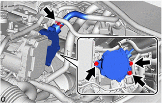
(b) Remove the 3 bolts and vacuum pump assembly from the engine assembly.
|
(c) Remove the No. 2 O-ring and No. 3 O-ring from the vacuum pump assembly. |
|
 On-vehicle Inspection
ON-VEHICLE INSPECTION
PROCEDURE
1. OPERATION CHECK
(a) Slide the clip and disconnect the union to connector tube hose from the vacuum
pump assembly.
(b) Connect the hose of a vacuum g ...
 Disassembly
DISASSEMBLY
PROCEDURE
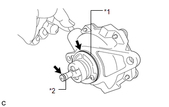
1. REMOVE END COVER
(a) Using a T25 "TORX" socket wrench, remove the 5 screws and end cover.
NOTICE:
Hold the vacuum pump assembly so t ...
Other materials:
Toyota CH-R Service Manual > General Maintenance: Chassis
CHASSIS
INSPECT STEERING LINKAGE AND GEAR HOUSING
(a) Check the steering wheel free play.
Click here
(b) Check the steering linkage for looseness or damage.
(1) Check that the tie rod ends do not have any play.
(2) Check that the dust seals and boots are not damaged.
(3) Check that the bo ...
Toyota CH-R Service Manual > Rear Seat Assembly: Removal
REMOVAL
CAUTION / NOTICE / HINT
CAUTION:
Wear protective gloves. Sharp areas on the parts may injure your hands.
PROCEDURE
1. REMOVE REAR SEAT HEADREST ASSEMBLY (for RH Side)
(a) Remove the rear seat headrest assembly.
2. REMOVE REAR SEAT HEADREST ASSEMBLY (for LH Side)
(a) Remove the rear s ...
Toyota C-HR (AX20) 2023-2026 Owner's Manual
Toyota CH-R Owners Manual
- For safety and security
- Instrument cluster
- Operation of each component
- Driving
- Interior features
- Maintenance and care
- When trouble arises
- Vehicle specifications
- For owners
Toyota CH-R Service Manual
- Introduction
- Maintenance
- Audio / Video
- Cellular Communication
- Navigation / Multi Info Display
- Park Assist / Monitoring
- Brake (front)
- Brake (rear)
- Brake Control / Dynamic Control Systems
- Brake System (other)
- Parking Brake
- Axle And Differential
- Drive Shaft / Propeller Shaft
- K114 Cvt
- 3zr-fae Battery / Charging
- Networking
- Power Distribution
- Power Assist Systems
- Steering Column
- Steering Gear / Linkage
- Alignment / Handling Diagnosis
- Front Suspension
- Rear Suspension
- Tire / Wheel
- Tire Pressure Monitoring
- Door / Hatch
- Exterior Panels / Trim
- Horn
- Lighting (ext)
- Mirror (ext)
- Window / Glass
- Wiper / Washer
- Door Lock
- Heating / Air Conditioning
- Interior Panels / Trim
- Lighting (int)
- Meter / Gauge / Display
- Mirror (int)
- Power Outlets (int)
- Pre-collision
- Seat
- Seat Belt
- Supplemental Restraint Systems
- Theft Deterrent / Keyless Entry

0.0072