Toyota CH-R Service Manual: Disposal
DISPOSAL
CAUTION / NOTICE / HINT
CAUTION:
Before performing pre-disposal deployment of any SRS part, review and closely follow all applicable environmental and hazardous material regulations. Pre-disposal deployment may be considered hazardous material treatment.
PROCEDURE
1. PRECAUTION
CAUTION:
- Use gloves and safety glasses when handling a rear 3 point type seat outer belt assembly with a deployed pretensioner.
- Always wash your hands with water after completing the operation.
- Do not apply water, etc. to a rear 3 point type seat outer belt assembly with a deployed pretensioner.
- When deploying a seat belt pretensioner, always use the specified SST (SRS airbag activation tool). Perform the operation in a place away from electrical noise.
- Never dispose of a rear 3 point type seat outer belt assembly with a pretensioner that has not been deployed.
- The rear 3 point type seat outer belt assembly produces an exploding sound when the pretensioner is deployed, so perform the operation outdoors where it will not disturb nearby residents.
- When deploying a seat belt pretensioner, perform the operation at least 10 m (32.8 ft.) away from the vehicle.
HINT:
When scrapping a vehicle equipped with a seat belt pretensioner or disposing of a rear 3 point type seat outer belt assembly with a seat belt pretensioner, always deploy the seat belt pretensioner first in accordance with the procedure described below. If any abnormality occurs during deployment of the seat belt pretensioner, contact the SERVICE DEPARTMENT of the distributor.
2. DISPOSE OF REAR 3 POINT TYPE SEAT OUTER BELT ASSEMBLY (When Installed to Vehicle)
NOTICE:
- When disposing of a rear 3 point type seat outer belt assembly with a pretensioner, never deploy the pretensioner in the customer's vehicle.
- Be sure to observe the following procedure when deploying a seat belt pretensioner.
HINT:
Prepare a battery as the power source to deploy the seat belt pretensioner.
|
(a) Check the function of SST. Click here SST: 09082-00700 |
|
.png)
(b) Refer to Precaution.
Click here .gif)
(c) Disconnect the cable from the negative (-) battery terminal.
CAUTION:
Wait at least 90 seconds after disconnecting the cable from the negative (-) battery terminal to disable the SRS system.
(d) Remove the roof side inner garnish assembly.
Click here
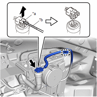
(e) Disconnect the seat belt pretensioner connector (for LH Side).
|
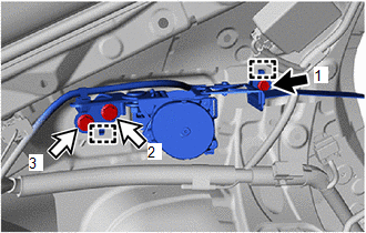
(1) Remove the 3 bolts. |
|
.png)
(2) Disengage the guides to separate the rear seat 3 point type outer belt assembly LH with bracket.
|
(3) Disengage the clamp. |
|
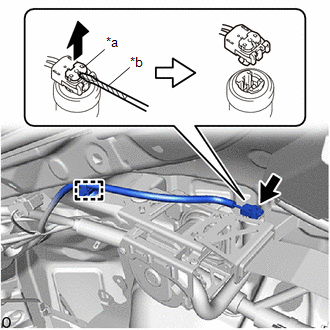
(4) Using a screwdriver with its tip wrapped in protective tape, pull out the locking button to release the lock to disconnect the pretensioner connector as shown in the illustration.
(f) Disconnect the seat belt pretensioner connector (for RH Side).
|
(1) Disengage the clamp. |
|
(2) Using a screwdriver with its tip wrapped in protective tape, pull out the locking button to release the lock to disconnect the pretensioner connector as shown in the illustration.
(g) Connect SST.
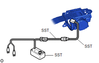
(1) After connecting the following SST to each other, connect them to the seat belt pretensioner.
SST: 09082-00700
SST: 09082-00802
09082-10801
09082-20801
NOTICE:
To avoid damaging the SST connector or wire harness, do not lock the secondary lock of the pretensioner connector.
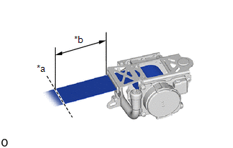
(2) Move SST at least 10 m (32.8 ft.) away from the front of the vehicle.
.png)
|
*a |
Battery |
|
*b |
10 m (32.8 ft.) or more |
CAUTION:
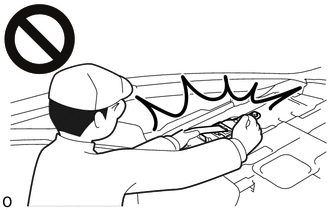
- Do not perform deployment with any of the doors or windows open.
.png)
- If deployment is performed with any of the doors or windows open, dust and gas may enter the eyes or be breathed in.
(3) Close all of the doors and windows of the vehicle.
NOTICE:
Do not damage the SST wire harness.
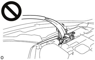
(h) Install rear seat 3 point type outer belt assembly LH (for LH Side).
(1) Engage the guides to temporarily install the rear seat 3 point type outer belt assembly LH with bracket.
.png) |
Bolt (A) |
.png) |
Bolt (B) |
(2) Temporarily install the 3 bolts.
(3) Tighten the 3 bolts in the order shown in the illustration.
Torque:
Bolt (A) :
12.5 N·m {127 kgf·cm, 9 ft·lbf}
Bolt (B) :
42 N·m {428 kgf·cm, 31 ft·lbf}
(i) Deploy the seat belt pretensioner.
|
(1) Check that no one is inside the vehicle or within a 10 m (32.8 ft.) radius of the vehicle. |
|
.png)
(2) Connect the red clip of SST to the positive (+) battery terminal and the black clip to the negative (-) battery terminal.
(3) Press the SST activation switch to deploy the seat belt pretensioner.
HINT:
The seat belt pretensioner will deploy at the same time as the LED of SST illuminates.
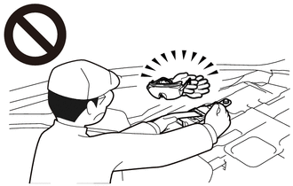
CAUTION:
- The rear 3 point type seat outer belt assembly produces an exploding
sound when the pretensioner is deployed, so perform the operation outdoors
where it will not disturb nearby residents.
.png)
- If this procedure is performed indoors or on a rough road where safety cannot be ensured, unforeseen injuries may occur. Also, if this procedure is performed near a residential area, the deployment noise may disturb nearby residents.
(j) Dispose of the rear 3 point type seat outer belt assembly.
(1) Remove the rear 3 point type seat outer belt assembly and SST.
(2) Place the rear 3 point type seat outer belt assembly in a plastic bag, tie the end tightly, and dispose of it according to local regulations.
CAUTION:
- The rear 3 point type seat outer belt assembly becomes extremely hot
when the pretensioner is deployed, so do not touch it for at least 30 minutes
after deployment.
- Do not apply water, etc. to a rear 3 point type seat outer belt assembly
with a deployed pretensioner.
- If water is applied to the rear 3 point type seat outer belt assembly immediately after deployment, burns may be caused by the resulting steam.
- Always wear safety glasses and gloves when handling a rear 3 point type
seat outer belt assembly with a deployed pretensioner.
- If a rear 3 point type seat outer belt assembly with a deployed pretensioner is touched without wearing safety glasses and gloves, hot parts may cause burns and dust may enter the eyes.
- After removal, quickly seal the rear 3 point type seat outer belt assembly in a plastic bag.
- Never dispose of a rear 3 point type seat outer belt assembly with a
pretensioner that has not been deployed.
.png)
- If a rear 3 point type seat outer belt assembly with a pretensioner that has not been deployed is disposed of, and then deploys accidentally, unforeseen injuries may occur.
- Always wash your hands with water after completing the operation.
HINT:
When scrapping a vehicle, deploy the seat belt pretensioners, and then scrap the vehicle with the front seat outer belt assemblies installed.
3. DISPOSE OF REAR 3 POINT TYPE SEAT OUTER BELT ASSEMBLY (When not Installed to Vehicle)
NOTICE:
- When disposing of a rear 3 point type seat outer belt assembly with a pretensioner, never deploy the pretensioner in the customer's vehicle.
- Be sure to observe the following procedure when deploying a seat belt pretensioner.
HINT:
Prepare a battery as the power source to deploy the seat belt pretensioner.
|
(a) Check the function of SST. Click here SST: 09082-00700 |
|
(b) Refer to Precaution.
Click here
(c) Disconnect the cable from the negative (-) battery terminal.
CAUTION:
Wait at least 90 seconds after disconnecting the cable from the negative (-) battery terminal to disable the SRS system.
(d) Remove the rear 3 point type seat outer belt assembly.
Click here
|
(e) Wind the seat belt webbing with the retractor. |
|
(f) When the seat belt webbing is sufficiently wound, cut the seat belt webbing approximately 100 mm (3.94 in.) from the retractor, as shown in the illustration.
HINT:
The retractor resistance increases in proportion with how much the seat belt webbing is wound.
|
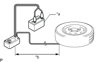
(g) Connect SST. (1) After connecting the following SST to each other, connect them to the seat belt pretensioner. SST: 09082-00700 SST: 09082-00802 09082-10801 09082-20801 NOTICE: To avoid damaging the SST connector or wire harness, do not lock the secondary lock of the pretensioner connector. (2) Place the rear 3 point type seat outer belt assembly on the ground and cover it with an unneeded tire and wheel assembly. NOTICE:
(3) Position and hold SST at least 10 m (32.8 ft.) away from the tire and wheel assembly. NOTICE: Do not damage the SST wire harness. |
|
(h) Deploy the seat belt pretensioner.
|
*a |
Battery |
|
*b |
10 m (32.8 ft.) or more |
(1) Check that no one is within a 10 m (32.8 ft.) radius of the tire and wheel assembly.
(2) Connect the red clip of SST to the positive (+) battery terminal and the black clip to the negative (-) battery terminal.
(3) Press the SST activation switch to deploy the seat belt pretensioner.
HINT:
The seat belt pretensioner will deploy at the same time as the LED of SST illuminates.
CAUTION:
- The rear 3 point type seat outer belt assembly produces an exploding
sound when the pretensioner is deployed, so perform the operation outdoors
where it will not disturb nearby residents.
.png)
- If this procedure is performed indoors or on a rough road where safety cannot be ensured, unforeseen injuries may occur. Also, if this procedure is performed near a residential area, the deployment noise may disturb nearby residents.
(i) Dispose of the rear 3 point type seat outer belt assembly.
(1) Remove the tire and wheel assembly and SST.
(2) Place the rear 3 point type seat outer belt assembly in a plastic bag, tie the end tightly, and dispose of it according to local regulations.
CAUTION:
- The rear 3 point type seat outer belt assembly becomes extremely hot
when the pretensioner is deployed, so do not touch it for at least 30 minutes
after deployment.
.png)
- Do not apply water, etc. to a rear 3 point type seat outer belt assembly
with a deployed pretensioner.
.png)
- If water is applied to the rear 3 point type seat outer belt assembly immediately after deployment, burns may be caused by the resulting steam.
- Always wear safety glasses and gloves when handling a rear 3 point type
seat outer belt assembly with a deployed pretensioner.
.png)
- If a rear 3 point type seat outer belt assembly with a deployed pretensioner is touched without wearing safety glasses and gloves, hot parts may cause burns and dust may enter the eyes.
- After removal, quickly seal the rear 3 point type seat outer belt assembly in a plastic bag.
- Never dispose of a rear 3 point type seat outer belt assembly with a
pretensioner that has not been deployed.
- If a rear 3 point type seat outer belt assembly with a pretensioner that has not been deployed is disposed of, and then deploys accidentally, unforeseen injuries may occur.
- Always wash your hands with water after completing the operation.
 Installation
INSTALLATION
CAUTION / NOTICE / HINT
HINT:
Use the same procedure for the RH side and LH side.
The procedure listed below is for the LH side.
PROCEDURE
1. INSPECT REAR SEAT 3 PO ...
 Seat Belt Warning Light
Components
COMPONENTS
ILLUSTRATION
*1
CLOCK ASSEMBLY
*2
INSTRUMENT CLUSTER FINISH CENTER PANEL SUB-ASSEMBLY
Removal
REMOVAL
CAUTION / N ...
Other materials:
Toyota CH-R Service Manual > 3zr-fae Coolant: Components
COMPONENTS
ILLUSTRATION
*1
RESERVE TANK CAP
*2
RADIATOR DRAIN COCK PLUG
*3
NO. 1 ENGINE UNDER COVER
-
-
N*m (kgf*cm, ft.*lbf): Specified torque
-
-
...
Toyota CH-R Service Manual > Vehicle Stability Control System: Precaution
PRECAUTION
IGNITION SWITCH EXPRESSION
HINT:
The type of ignition switch used on this model differs according to the specifications
of the vehicle. The expressions listed in the table below are used in this section.
Expression
Ignition Switch (Position)
Engine S ...
Toyota C-HR (AX20) 2023-2026 Owner's Manual
Toyota CH-R Owners Manual
- For safety and security
- Instrument cluster
- Operation of each component
- Driving
- Interior features
- Maintenance and care
- When trouble arises
- Vehicle specifications
- For owners
Toyota CH-R Service Manual
- Introduction
- Maintenance
- Audio / Video
- Cellular Communication
- Navigation / Multi Info Display
- Park Assist / Monitoring
- Brake (front)
- Brake (rear)
- Brake Control / Dynamic Control Systems
- Brake System (other)
- Parking Brake
- Axle And Differential
- Drive Shaft / Propeller Shaft
- K114 Cvt
- 3zr-fae Battery / Charging
- Networking
- Power Distribution
- Power Assist Systems
- Steering Column
- Steering Gear / Linkage
- Alignment / Handling Diagnosis
- Front Suspension
- Rear Suspension
- Tire / Wheel
- Tire Pressure Monitoring
- Door / Hatch
- Exterior Panels / Trim
- Horn
- Lighting (ext)
- Mirror (ext)
- Window / Glass
- Wiper / Washer
- Door Lock
- Heating / Air Conditioning
- Interior Panels / Trim
- Lighting (int)
- Meter / Gauge / Display
- Mirror (int)
- Power Outlets (int)
- Pre-collision
- Seat
- Seat Belt
- Supplemental Restraint Systems
- Theft Deterrent / Keyless Entry

0.0119