Toyota CH-R Service Manual: Installation
INSTALLATION
CAUTION / NOTICE / HINT
HINT:
- Use the same procedure for the RH side and LH side.
- The procedure listed below is for the LH side.
PROCEDURE
1. INSPECT REAR SEAT 3 POINT TYPE OUTER BELT ASSEMBLY
Click here .gif)
2. INSTALL REAR SEAT 3 POINT TYPE OUTER BELT ASSEMBLY LH (for LH Side)
(a) w/o Pretensioner and Force Limiter:
|
(1) Engage the guides to install the rear seat 3 point type outer belt assembly LH to the outer belt anchor bracket sub-assembly LH. |
|
.png)
(2) Temporarily install the nut.
(3) Engage the guides to temporarily install the rear seat 3 point type outer belt assembly LH with bracket.
.png) |
Bolt (A) |
.png) |
Bolt (B) |
(4) Temporarily install the 3 bolts.
(5) Tighten the 3 bolts in the order shown in the illustration.
Torque:
Bolt (A) :
12.5 N·m {127 kgf·cm, 9 ft·lbf}
Bolt (B) :
42 N·m {428 kgf·cm, 31 ft·lbf}
(6) Tighten the nut.
Torque:
42 N·m {428 kgf·cm, 31 ft·lbf}
(7) Check that the ELR locks.
NOTICE:
This check should be performed with the rear seat 3 point type outer belt assembly LH installed to the vehicle.
- With the rear 3 point type seat outer belt assembly LH installed to the vehicle, check that the belt locks when it is pulled out quickly.
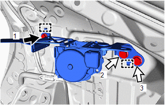
(b) w/ Pretensioner and Force Limiter:
|
(1) Engage the guides to install the rear seat 3 point type outer belt assembly LH to the outer belt anchor bracket sub-assembly LH. |
|
.png)
(2) Temporarily install the nut.
|
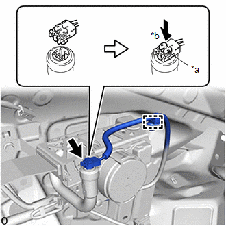
(3) Connect the pretensioner connector and lock the locking button as shown in the illustration. NOTICE: Securely lock the locking button. |
|
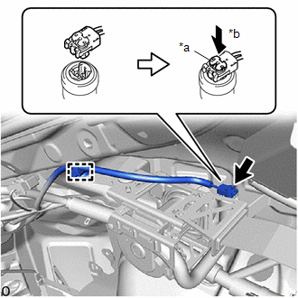
(4) Engage the clamp.
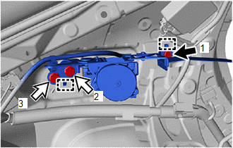
(5) Engage the guides to temporarily install the rear seat 3 point type outer belt assembly LH with bracket.
|
|
Bolt (A) |
|
|
Bolt (B) |
(6) Temporarily install the 3 bolts.
(7) Tighten the 3 bolts in the order shown in the illustration.
Torque:
Bolt (A) :
12.5 N·m {127 kgf·cm, 9 ft·lbf}
Bolt (B) :
42 N·m {428 kgf·cm, 31 ft·lbf}
(8) Tighten the nut.
Torque:
42 N·m {428 kgf·cm, 31 ft·lbf}
(9) Check that the ELR locks.
NOTICE:
This check should be performed with the rear seat 3 point type outer belt assembly LH installed to the vehicle.
- With the rear seat 3 point type outer belt assembly LH installed to the vehicle, check that the belt locks when it is pulled out quickly.
|
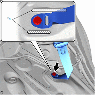
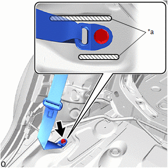
(c) Connect the floor anchor of the rear seat 3 point type outer belt assembly LH with the bolt. Torque: 42 N·m {428 kgf·cm, 31 ft·lbf} NOTICE: Do not allow the anchor part of the rear seat 3 point type outer belt assembly LH to overlap the protruding parts of the floor panel. |
|
3. INSTALL REAR SEAT 3 POINT TYPE OUTER BELT ASSEMBLY RH (for RH Side)
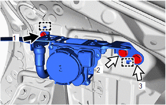
(a) w/o Pretensioner and Force Limiter:
|
(1) Engage the guides to install the rear seat 3 point type outer belt assembly RH to the outer belt anchor bracket sub-assembly RH. |
|
.png)
(2) Temporarily install the nut.
(3) Engage the guides to temporarily install the rear seat 3 point type outer belt assembly RH with bracket.
|
|
Bolt (A) |
|
|
Bolt (B) |
(4) Temporarily install the 3 bolts.
(5) Tighten the 3 bolts in the order shown in the illustration.
Torque:
Bolt (A) :
12.5 N·m {127 kgf·cm, 9 ft·lbf}
Bolt (B) :
42 N·m {428 kgf·cm, 31 ft·lbf}
(6) Tighten the nut.
Torque:
42 N·m {428 kgf·cm, 31 ft·lbf}
(7) Check that the ELR locks.
NOTICE:
This check should be performed with the rear seat 3 point type outer belt assembly RH installed to the vehicle.
- With the rear seat 3 point type outer belt assembly RH installed to the vehicle, check that the belt locks when it is pulled out quickly.
(b) w/ Pretensioner and Force Limiter:
|
(1) Engage the guides to install the rear seat 3 point type outer belt assembly RH to the outer belt anchor bracket sub-assembly RH. |
|
.png)
(2) Temporarily install the nut.
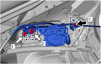
(3) Engage the guides to temporarily install the rear seat 3 point type outer belt assembly RH with bracket.
|
|
Bolt (A) |
|
|
Bolt (B) |
(4) Temporarily install the 3 bolts.
(5) Tighten the 3 bolts in the order shown in the illustration.
Torque:
Bolt (A) :
12.5 N·m {127 kgf·cm, 9 ft·lbf}
Bolt (B) :
42 N·m {428 kgf·cm, 31 ft·lbf}
(6) Tighten the nut.
Torque:
42 N·m {428 kgf·cm, 31 ft·lbf}
|
(7) Connect the pretensioner connector and lock the locking button as shown in the illustration. NOTICE: Securely lock the locking button. |
|
(8) Engage the clamp.
(9) Check that the ELR locks.
NOTICE:
This check should be performed with the rear seat 3 point type outer belt assembly RH installed to the vehicle.
- With the rear seat 3 point type outer belt assembly RH installed to the vehicle, check that the belt locks when it is pulled out quickly.
|
(c) Connect the floor anchor of the rear seat 3 point type outer belt assembly RH with the bolt. Torque: 42 N·m {428 kgf·cm, 31 ft·lbf} NOTICE: Do not allow the anchor part of the rear seat 3 point type outer belt assembly RH to overlap the protruding parts of the floor panel. |
|
4. INSTALL ROOF SIDE INNER GARNISH ASSEMBLY
Click here
5. INSTALL DECK TRIM SIDE PANEL ASSEMBLY
Click here
6. INSTALL NO. 1 LUGGAGE COMPARTMENT LIGHT ASSEMBLY
Click here
7. INSTALL DECK TRIM REAR COVER
Click here
8. INSTALL REAR SEAT SIDE GARNISH (w/o Rear Seat Side Airbag)
Click here
9. INSTALL REAR SEAT SIDE GARNISH (w/ Rear Seat Side Airbag)
Click here
10. INSTALL REAR PILLAR COVER (w/ Rear Seat Side Airbag)
Click here
11. INSTALL REAR SEATBACK HINGE SUB-ASSEMBLY
Click here
12. INSTALL REAR DOOR OPENING TRIM WEATHERSTRIP
Click here
13. INSTALL REAR DOOR SCUFF PLATE (w/o Rear Seat Side Airbag)
Click here
14. INSTALL REAR DOOR SCUFF PLATE (w/ Rear Seat Side Airbag)
Click here
15. INSTALL DECK FLOOR BOX LH
Click here
16. INSTALL DECK FLOOR BOX RH
Click here
17. INSTALL SPARE WHEEL CUSHION
Click here
18. INSTALL DECK BOARD ASSEMBLY
Click here
19. INSTALL TONNEAU COVER ASSEMBLY (w/ Tonneau Cover)
Click here
20. INSTALL PACKAGE TRAY TRIM PANEL ASSEMBLY (w/ Package Tray Trim)
Click here
21. INSTALL REAR SEAT ASSEMBLY
Click here
 Inspection
INSPECTION
PROCEDURE
1. INSPECT REAR SEAT 3 POINT TYPE OUTER BELT ASSEMBLY
(a) Before installing the rear seat 3 point type outer belt assembly,
check the ELR function.
NOTICE:
...
 Disposal
DISPOSAL
CAUTION / NOTICE / HINT
CAUTION:
Before performing pre-disposal deployment of any SRS part, review and closely
follow all applicable environmental and hazardous material regulations. Pre ...
Other materials:
Toyota CH-R Service Manual > Front Airbag Sensor: On-vehicle Inspection
ON-VEHICLE INSPECTION
CAUTION / NOTICE / HINT
CAUTION:
Be sure to correctly follow the removal and installation procedures for the front
airbag sensors.
PROCEDURE
1. INSPECT FRONT AIRBAG SENSOR (for Vehicle not Involved in Collision)
(a) Perform a diagnostic system check.
Click here
2. I ...
Toyota CH-R Service Manual > Washer Level Warning Switch: Inspection
INSPECTION
PROCEDURE
1. INSPECT LEVEL WARNING SWITCH ASSEMBLY
HINT:
This check should be performed with the level warning switch assembly installed
on the washer jar.
(a) Fill the washer jar with washer fluid.
...
Toyota C-HR (AX20) 2023-2026 Owner's Manual
Toyota CH-R Owners Manual
- For safety and security
- Instrument cluster
- Operation of each component
- Driving
- Interior features
- Maintenance and care
- When trouble arises
- Vehicle specifications
- For owners
Toyota CH-R Service Manual
- Introduction
- Maintenance
- Audio / Video
- Cellular Communication
- Navigation / Multi Info Display
- Park Assist / Monitoring
- Brake (front)
- Brake (rear)
- Brake Control / Dynamic Control Systems
- Brake System (other)
- Parking Brake
- Axle And Differential
- Drive Shaft / Propeller Shaft
- K114 Cvt
- 3zr-fae Battery / Charging
- Networking
- Power Distribution
- Power Assist Systems
- Steering Column
- Steering Gear / Linkage
- Alignment / Handling Diagnosis
- Front Suspension
- Rear Suspension
- Tire / Wheel
- Tire Pressure Monitoring
- Door / Hatch
- Exterior Panels / Trim
- Horn
- Lighting (ext)
- Mirror (ext)
- Window / Glass
- Wiper / Washer
- Door Lock
- Heating / Air Conditioning
- Interior Panels / Trim
- Lighting (int)
- Meter / Gauge / Display
- Mirror (int)
- Power Outlets (int)
- Pre-collision
- Seat
- Seat Belt
- Supplemental Restraint Systems
- Theft Deterrent / Keyless Entry

0.0088