Toyota CH-R Service Manual: Vanity Light Switch
Components
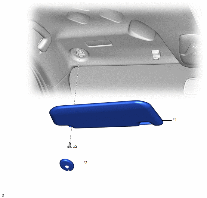
COMPONENTS
ILLUSTRATION
|
*1 |
VISOR ASSEMBLY |
*2 |
VISOR BRACKET COVER |
Inspection
INSPECTION
PROCEDURE
1. INSPECT VISOR ASSEMBLY LH
|
(a) Check the resistance. (1) Measure the resistance according to the value(s) in the table below. Standard Resistance:
If the result is not as specified, replace the visor assembly LH. |
|
2. INSPECT VISOR ASSEMBLY RH
|
(a) Check the resistance. (1) Measure the resistance according to the value(s) in the table below. Standard Resistance:
If the result is not as specified, replace the visor assembly RH. |
|
Removal
REMOVAL
CAUTION / NOTICE / HINT
HINT:
- Use the same procedure as for the LH and RH sides.
- The procedure described below is for the LH side.
PROCEDURE
1. REMOVE VISOR BRACKET COVER
Click here .gif)
2. REMOVE VISOR ASSEMBLY
|
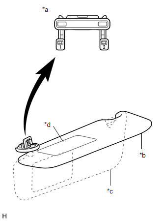
(a) Using a T10H "TORX" driver, remove the 2 screws. |
|
.png)
(b) Disengage the guide to remove the visor assembly.
Installation
INSTALLATION
CAUTION / NOTICE / HINT
HINT:
- Use the same procedure as for the LH and RH sides.
- The procedure described below is for the LH side.
PROCEDURE
1. INSTALL VISOR ASSEMBLY
|
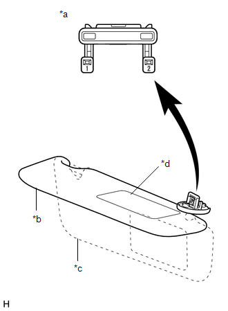
(a) Engage the guide to install the visor assembly. |
|
.png)
(b) Using a T10H "TORX" driver, install the 2 screws.
2. INSTALL VISOR BRACKET COVER
Click here .gif)
 Vanity Light Bulb
Replacement
REPLACEMENT
CAUTION / NOTICE / HINT
HINT:
Use the same procedure for both the LH and RH sides.
The procedure described below is for the LH side.
PROCEDURE
1. REMO ...

Other materials:
Toyota CH-R Service Manual > Rear Combination Light Assembly(for Bulb Type): Reassembly
REASSEMBLY
CAUTION / NOTICE / HINT
HINT:
Use the same procedure for the RH side and LH side.
The following procedure is for the LH side.
PROCEDURE
1. INSTALL REAR COMBINATION LIGHT SOCKET AND WIRE
(a) Connect the connector.
...
Toyota CH-R Service Manual > Airbag System: Parts Location
PARTS LOCATION
ILLUSTRATION
*1
FRONT AIRBAG SENSOR LH
*2
FRONT AIRBAG SENSOR RH
*3
DOOR SIDE AIRBAG SENSOR LH
*4
DOOR SIDE AIRBAG SENSOR RH
*5
NO. 1 SIDE AIRBAG SENSOR LH
...
Toyota C-HR (AX20) 2023-2026 Owner's Manual
Toyota CH-R Owners Manual
- For safety and security
- Instrument cluster
- Operation of each component
- Driving
- Interior features
- Maintenance and care
- When trouble arises
- Vehicle specifications
- For owners
Toyota CH-R Service Manual
- Introduction
- Maintenance
- Audio / Video
- Cellular Communication
- Navigation / Multi Info Display
- Park Assist / Monitoring
- Brake (front)
- Brake (rear)
- Brake Control / Dynamic Control Systems
- Brake System (other)
- Parking Brake
- Axle And Differential
- Drive Shaft / Propeller Shaft
- K114 Cvt
- 3zr-fae Battery / Charging
- Networking
- Power Distribution
- Power Assist Systems
- Steering Column
- Steering Gear / Linkage
- Alignment / Handling Diagnosis
- Front Suspension
- Rear Suspension
- Tire / Wheel
- Tire Pressure Monitoring
- Door / Hatch
- Exterior Panels / Trim
- Horn
- Lighting (ext)
- Mirror (ext)
- Window / Glass
- Wiper / Washer
- Door Lock
- Heating / Air Conditioning
- Interior Panels / Trim
- Lighting (int)
- Meter / Gauge / Display
- Mirror (int)
- Power Outlets (int)
- Pre-collision
- Seat
- Seat Belt
- Supplemental Restraint Systems
- Theft Deterrent / Keyless Entry

0.0073