Toyota CH-R Service Manual: Brake Hold Standby Indicator Light Circuit
DESCRIPTION
When the brake hold switch (electric parking brake switch assembly) is turned on with the ignition switch turned to ON, the brake hold standby indicator light illuminates when brake hold operation is possible.
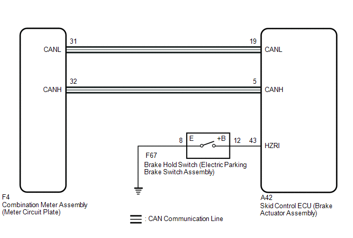
WIRING DIAGRAM
CAUTION / NOTICE / HINT
HINT:
When replacing the skid control ECU (brake actuator assembly), perform zero point calibration and store system information.
Click here
.gif)
PROCEDURE
|
1. |
PRE-CHECK |
(a) If the brake hold standby indicator light does not illuminate even though the brake hold switch (electric parking brake switch assembly) is pushed, check that the brake hold function operation conditions are met.
- The driver's door is closed.
- Driver's seat belt is fastened.
- The engine hood is closed.
- The back door is closed.
- The system is normal.
|
.gif)
|
2. |
CHECK CAN COMMUNICATION SYSTEM |
(a) Check if CAN communication system DTCs are output.
Click here
|
Result |
Proceed to |
|---|---|
|
DTCs are not output. |
A |
|
DTCs are output. |
B |
| B | .gif) |
CHECK CAN COMMUNICATION SYSTEM
|
|
|
3. |
CHECK IF BRAKE ACTUATOR ASSEMBLY CONNECTOR IS SECURELY CONNECTED |
(a) Jiggle the skid control ECU (brake actuator assembly) connectors and wire harnesses vertically and horizontally and check the brake hold standby indicator light status.
OK:
The connector is securely connected.
| NG | |
CONNECT CONNECTOR TO BRAKE ACTUATOR ASSEMBLY CORRECTLY |
|
|
4. |
INSPECT COMBINATION METER ASSEMBLY |
(a) Connect the Techstream to the DLC3.
(b) Turn the ignition switch off.
(c) Perform the Active Test of the combination meter assembly using the Techstream.
Click here
|
Tester Display |
|---|
|
Indicat. Brake Hold |
(d) Check the combination meter assembly.
OK:
The brake hold standby indicator light turns on or off in accordance with the Techstream operation.
| NG | |
INSPECT METER / GAUGE SYSTEM |
|
|
5. |
PERFORM ACTIVE TEST USING TECHSTREAM (BRAKE HOLD STANDBY INDICATOR LIGHT) |
(a) Turn the ignition switch to ON.
(b) Select the Active Test on the Techstream.
Click here
|
Tester Display |
Measurement Item |
Control Range |
Diagnostic Note |
|---|---|---|---|
|
BH Standby Light |
Brake hold standby indicator light |
Indicator light ON/OFF |
Observe combination meter |
(c) Select the Data List on the Techstream.
Click here
|
Tester Display |
Measurement Item |
Range |
Normal Condition |
Diagnostic Note |
|---|---|---|---|---|
|
BH Standby Light |
Brake hold standby indicator light |
ON or OFF |
ON: Indicator light on OFF: Indicator light off |
- |
|
Active Test Display |
|---|
|
BH Standby Light |
|
Data List Display |
|---|
|
BH Standby Light |
(d) Check the operating condition of the brake hold standby indicator light when operating it using the Techstream.
|
Result |
Proceed to |
|---|---|
|
Brake hold standby indicator light in the Data List does not change using the Active Test. |
A |
|
Brake hold standby indicator light in the Data List turns ON/OFF using the Active Test. |
B |
| A | |
REPLACE BRAKE ACTUATOR ASSEMBLY |
|
|
6. |
INSPECT ELECTRIC PARKING BRAKE SWITCH ASSEMBLY |
(a) Inspect the electric parking brake switch assembly.
Click here
| NG | |
REPLACE ELECTRIC PARKING BRAKE SWITCH ASSEMBLY |
|
|
7. |
CHECK HARNESS AND CONNECTOR (BRAKE ACTUATOR ASSEMBLY - ELECTRIC PARKING BRAKE SWITCH ASSEMBLY) |
(a) Disconnect the A42 skid control ECU (brake actuator assembly) connector.
(b) Measure the resistance according to the value(s) in the table below.
Standard Resistance:
|
Tester Connection |
Condition |
Specified Condition |
|---|---|---|
|
A42-43 (HZRI) - F67-12 (+B) |
Always |
Below 1 Ω |
|
A42-43 (HZRI) or F67-12 (+B) - Body ground |
Always |
10 kΩ or higher |
|
F67-8 (E) - Body ground |
Always |
Below 1 Ω |
| OK | |
REPLACE BRAKE ACTUATOR ASSEMBLY |
| NG | |
REPAIR OR REPLACE HARNESS OR CONNECTOR |
 Brake Hold Operated Indicator Light Circuit
DESCRIPTION
The brake hold operated indicator light illuminates when the brake hold system
is operating (vehicle stopped due to brake fluid pressure hold) and turns off when
the brake hold system ...
 Slip Indicator Light Remains ON
DESCRIPTION
The skid control ECU (brake actuator assembly) is connected to the combination
meter assembly via CAN communication.
The slip indicator light blinks during VSC and/or TRAC operation.
...
Other materials:
Toyota CH-R Service Manual > Smart Key System(for Entry Function): How To Proceed With Troubleshooting
CAUTION / NOTICE / HINT
HINT:
Use these procedures to troubleshoot the smart key system (for Entry
Function).
*: Use the Techstream.
PROCEDURE
1.
VEHICLE BROUGHT TO WORKSHOP
NEXT
...
Toyota CH-R Service Manual > Rear Seat Assembly: Reassembly
REASSEMBLY
CAUTION / NOTICE / HINT
CAUTION:
Wear protective gloves. Sharp areas on the parts may injure your hands.
PROCEDURE
1. INSTALL BENCH TYPE REAR SEAT CUSHION COVER
NOTICE:
When installing a bench type rear seat cushion cover, refer to Precaution in
order to prevent wrinkles from for ...
Toyota C-HR (AX20) 2023-2026 Owner's Manual
Toyota CH-R Owners Manual
- For safety and security
- Instrument cluster
- Operation of each component
- Driving
- Interior features
- Maintenance and care
- When trouble arises
- Vehicle specifications
- For owners
Toyota CH-R Service Manual
- Introduction
- Maintenance
- Audio / Video
- Cellular Communication
- Navigation / Multi Info Display
- Park Assist / Monitoring
- Brake (front)
- Brake (rear)
- Brake Control / Dynamic Control Systems
- Brake System (other)
- Parking Brake
- Axle And Differential
- Drive Shaft / Propeller Shaft
- K114 Cvt
- 3zr-fae Battery / Charging
- Networking
- Power Distribution
- Power Assist Systems
- Steering Column
- Steering Gear / Linkage
- Alignment / Handling Diagnosis
- Front Suspension
- Rear Suspension
- Tire / Wheel
- Tire Pressure Monitoring
- Door / Hatch
- Exterior Panels / Trim
- Horn
- Lighting (ext)
- Mirror (ext)
- Window / Glass
- Wiper / Washer
- Door Lock
- Heating / Air Conditioning
- Interior Panels / Trim
- Lighting (int)
- Meter / Gauge / Display
- Mirror (int)
- Power Outlets (int)
- Pre-collision
- Seat
- Seat Belt
- Supplemental Restraint Systems
- Theft Deterrent / Keyless Entry

0.0088