Toyota CH-R Service Manual: Slip Indicator Light Remains ON
DESCRIPTION
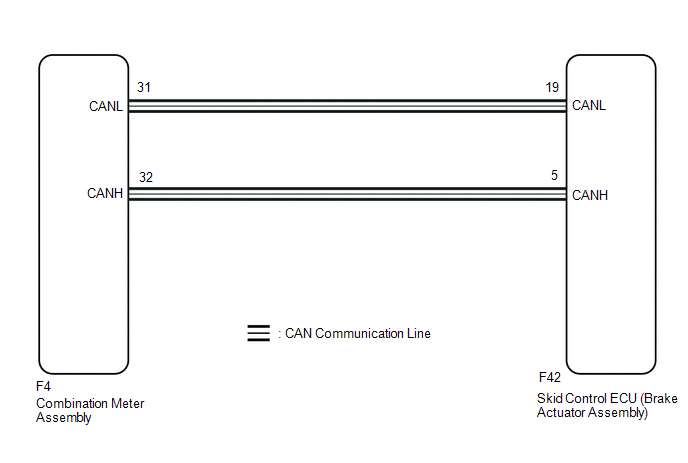
The skid control ECU (brake actuator assembly) is connected to the combination meter assembly via CAN communication.
The slip indicator light blinks during VSC and/or TRAC operation.
If a malfunction is detected, the slip indicator light comes on to warn the driver.
Click here
.gif)
WIRING DIAGRAM
CAUTION / NOTICE / HINT
NOTICE:
When replacing the skid control ECU (brake actuator assembly), perform system variant learning.
Click here
PROCEDURE
|
1. |
CHECK CAN COMMUNICATION SYSTEM |
(a) Check if CAN communication system DTCs are output.
Click here
|
Result |
Proceed to |
|---|---|
|
DTCs are not output. |
A |
|
DTCs are output. |
B |
| B | .gif) |
INSPECT CAN COMMUNICATION SYSTEM
|
|
.gif)
|
2. |
CHECK IF BRAKE ACTUATOR ASSEMBLY CONNECTOR IS SECURELY CONNECTED |
(a) Check if the skid control ECU (brake actuator assembly) connector is securely connected.
OK:
The connector is securely connected.
| NG | |
CONNECT CONNECTOR TO ECU CORRECTLY |
|
|
3. |
CHECK BATTERY |
(a) Check the battery voltage.
Standard Voltage:
11 to 14 V
| NG | |
CHECK OR REPLACE CHARGING SYSTEM COMPONENT OR BATTERY |
|
|
4. |
INSPECT COMBINATION METER ASSEMBLY |
(a) Perform an Active Test of the combination meter assembly using the Techstream.
Click here
|
Tester Display |
|---|
|
Indicat. Lamp Slip |
(b) Check the combination meter assembly.
OK:
The slip indicator light turns on or off in accordance with the Active Test operation.
HINT:
If troubleshooting has been carried out according to Problem Symptoms Table, refer back to the table and proceed to the next step before replacing parts.
Click here
| OK | |
REPLACE BRAKE ACTUATOR ASSEMBLY |
| NG | |
INSPECT METER / GAUGE SYSTEM |
 Brake Hold Standby Indicator Light Circuit
DESCRIPTION
When the brake hold switch (electric parking brake switch assembly) is turned
on with the ignition switch turned to ON, the brake hold standby indicator light
illuminates when brake h ...
 Slip Indicator Light does not Come ON
DESCRIPTION
The skid control ECU (brake actuator assembly) is connected to the combination
meter assembly via CAN communication.
CAUTION / NOTICE / HINT
NOTICE:
When replacing the skid control E ...
Other materials:
Toyota CH-R Service Manual > Washer Motor: Inspection
INSPECTION
PROCEDURE
1. INSPECT WINDSHIELD WASHER MOTOR AND PUMP ASSEMBLY (for Front Side)
HINT:
This check should be performed with the windshield washer motor and pump assembly
installed to the windshield washer jar assembly.
(a) Fill the windshield washer jar assembly with washer fluid.
...
Toyota CH-R Service Manual > Airbag System: Parts Location
PARTS LOCATION
ILLUSTRATION
*1
FRONT AIRBAG SENSOR LH
*2
FRONT AIRBAG SENSOR RH
*3
DOOR SIDE AIRBAG SENSOR LH
*4
DOOR SIDE AIRBAG SENSOR RH
*5
NO. 1 SIDE AIRBAG SENSOR LH
...
Toyota C-HR (AX20) 2023-2026 Owner's Manual
Toyota CH-R Owners Manual
- For safety and security
- Instrument cluster
- Operation of each component
- Driving
- Interior features
- Maintenance and care
- When trouble arises
- Vehicle specifications
- For owners
Toyota CH-R Service Manual
- Introduction
- Maintenance
- Audio / Video
- Cellular Communication
- Navigation / Multi Info Display
- Park Assist / Monitoring
- Brake (front)
- Brake (rear)
- Brake Control / Dynamic Control Systems
- Brake System (other)
- Parking Brake
- Axle And Differential
- Drive Shaft / Propeller Shaft
- K114 Cvt
- 3zr-fae Battery / Charging
- Networking
- Power Distribution
- Power Assist Systems
- Steering Column
- Steering Gear / Linkage
- Alignment / Handling Diagnosis
- Front Suspension
- Rear Suspension
- Tire / Wheel
- Tire Pressure Monitoring
- Door / Hatch
- Exterior Panels / Trim
- Horn
- Lighting (ext)
- Mirror (ext)
- Window / Glass
- Wiper / Washer
- Door Lock
- Heating / Air Conditioning
- Interior Panels / Trim
- Lighting (int)
- Meter / Gauge / Display
- Mirror (int)
- Power Outlets (int)
- Pre-collision
- Seat
- Seat Belt
- Supplemental Restraint Systems
- Theft Deterrent / Keyless Entry

0.0078