Toyota CH-R Service Manual: ABS Warning Light Remains ON
DESCRIPTION
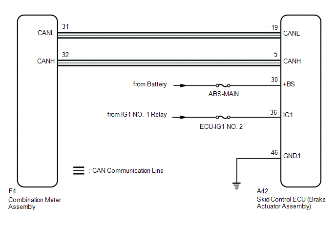
The skid control ECU (brake actuator assembly) is connected to the combination meter assembly via CAN communication. If any of the following is detected, the ABS warning light remains on:
- The skid control ECU (brake actuator assembly) connector is disconnected from the skid control ECU (brake actuator assembly).
- There is a malfunction in the skid control ECU (brake actuator assembly) internal circuit.
- There is an open in the harness between the combination meter and skid control ECU (brake actuator assembly).
- The ABS is defective.
HINT:
In some cases, the Techstream cannot be used when the skid control ECU (brake actuator assembly) is abnormal.
WIRING DIAGRAM
CAUTION / NOTICE / HINT
NOTICE:
- When replacing the skid control ECU (brake actuator assembly), perform
system variant learning.
Click here
.gif)
- Inspect the fuses for circuits related to this system before performing the following procedure.
PROCEDURE
|
1. |
CHECK CAN COMMUNICATION SYSTEM |
(a) Check if CAN communication system DTCs are output.
Click here
|
Result |
Proceed to |
|---|---|
|
DTCs are not output. |
A |
|
DTCs are output. |
B |
| B | .gif) |
INSPECT CAN COMMUNICATION SYSTEM
|
|
.gif)
|
2. |
CHECK IF BRAKE ACTUATOR ASSEMBLY CONNECTOR IS SECURELY CONNECTED |
(a) Check if the skid control ECU (brake actuator assembly) connector is securely connected.
OK:
The connector is securely connected.
| NG | |
CONNECT CONNECTOR TO ECU CORRECTLY |
|
|
3. |
CHECK BATTERY |
(a) Check the battery voltage.
Standard Voltage:
11 to 14 V
| NG | |
CHECK OR REPLACE CHARGING SYSTEM COMPONENT OR BATTERY |
|
|
4. |
CHECK HARNESS AND CONNECTOR (POWER SOURCE (IG1) TERMINAL) |
|
(a) Disconnect the A42 skid control ECU (brake actuator assembly) connector. |
|
.png)
(b) Measure the voltage according to the value(s) in the table below.
Standard Voltage:
|
Tester Connection |
Condition |
Specified Condition |
|---|---|---|
|
A42-30 (+BS) - Body ground |
Always |
11 to 14 V |
| NG | |
REPAIR OR REPLACE HARNESS OR CONNECTOR (POWER SOURCE TERMINAL) |
|
|
5. |
CHECK HARNESS AND CONNECTOR (POWER SOURCE (IG1) TERMINAL) |
|
(a) Disconnect the A42 skid control ECU (brake actuator assembly) connector. |
|
.png)
(b) Measure the voltage according to the value(s) in the table below.
Standard Voltage:
|
Tester Connection |
Condition |
Specified Condition |
|---|---|---|
|
A42-36 (IG1) - Body ground |
Ignition switch ON |
11 to 14 V |
| NG | |
REPAIR OR REPLACE HARNESS OR CONNECTOR (POWER SOURCE TERMINAL) |
|
|
6. |
CHECK HARNESS AND CONNECTOR (GND1 TERMINAL) |
|
(a) Turn the ignition switch off. |
|
.png)
(b) Measure the resistance according to the value(s) in the table below.
Standard Resistance:
|
Tester Connection |
Condition |
Specified Condition |
|---|---|---|
|
A42-46 (GND1) - Body ground |
Always |
Below 1 Ω |
| NG | |
REPAIR OR REPLACE HARNESS OR CONNECTOR (GND1 CIRCUIT) |
|
|
7. |
READ VALUE USING TECHSTREAM (ABS WARNING LIGHT) |
(a) Reconnect the A42 skid control ECU (brake actuator assembly) connector.
(b) Select the Data List on the Techstream.
Click here
|
Tester Display |
Measurement Item |
Range |
Normal Condition |
Diagnostic Note |
|---|---|---|---|---|
|
ABS Warning Light |
ABS warning light |
ON or OFF |
ON: Warning light on OFF: Warning light off |
- |
|
Tester Display |
|---|
|
ABS Warning Light |
(c) Check the Techstream display condition of the ABS warning light.
|
Result |
Proceed to |
|---|---|
|
ON is displayed. |
A |
|
OFF is displayed. |
B |
| A | |
REPLACE BRAKE ACTUATOR ASSEMBLY |
| B | |
INSPECT METER / GAUGE SYSTEM |
 NE Signal (C1224)
DESCRIPTION
The skid control ECU (brake actuator assembly) receives engine speed signals
from the ECM via CAN communication.
DTC No.
Detection Item
DTC Detection C ...
 Engine Control System Malfunction (C1201)
DESCRIPTION
If a malfunction in the SFI system is detected, the operation of VSC and TRAC
is prohibited by the fail-safe function. When the signals from the engine are received
normally, fail-saf ...
Other materials:
Toyota CH-R Service Manual > Washer Level Warning Switch: Removal
REMOVAL
PROCEDURE
1. REMOVE FRONT WHEEL RH
Click here
2. REMOVE ROCKER PANEL MOULDING RH
Click here
3. REMOVE FRONT FENDER MOULDING SUB-ASSEMBLY RH
Click here
4. REMOVE FRONT WHEEL OPENING EXTENSION PAD RH
Click here
5. REMOVE FRONT FENDER LINER RH
Click here
6. DRA ...
Toyota CH-R Service Manual > 3zr-fae Battery / Charging: Battery
Components
COMPONENTS
ILLUSTRATION
*1
BATTERY
*2
NO. 2 BATTERY CLAMP
*3
POSITIVE BATTERY TERMINAL
*4
NEGATIVE BATTERY TERMINAL
*5
FUSIBLE LINK COVER
*6
...
Toyota C-HR (AX20) 2023-2026 Owner's Manual
Toyota CH-R Owners Manual
- For safety and security
- Instrument cluster
- Operation of each component
- Driving
- Interior features
- Maintenance and care
- When trouble arises
- Vehicle specifications
- For owners
Toyota CH-R Service Manual
- Introduction
- Maintenance
- Audio / Video
- Cellular Communication
- Navigation / Multi Info Display
- Park Assist / Monitoring
- Brake (front)
- Brake (rear)
- Brake Control / Dynamic Control Systems
- Brake System (other)
- Parking Brake
- Axle And Differential
- Drive Shaft / Propeller Shaft
- K114 Cvt
- 3zr-fae Battery / Charging
- Networking
- Power Distribution
- Power Assist Systems
- Steering Column
- Steering Gear / Linkage
- Alignment / Handling Diagnosis
- Front Suspension
- Rear Suspension
- Tire / Wheel
- Tire Pressure Monitoring
- Door / Hatch
- Exterior Panels / Trim
- Horn
- Lighting (ext)
- Mirror (ext)
- Window / Glass
- Wiper / Washer
- Door Lock
- Heating / Air Conditioning
- Interior Panels / Trim
- Lighting (int)
- Meter / Gauge / Display
- Mirror (int)
- Power Outlets (int)
- Pre-collision
- Seat
- Seat Belt
- Supplemental Restraint Systems
- Theft Deterrent / Keyless Entry

0.007