Toyota CH-R Service Manual: Speed Sensor Rotor Faulty (C1237)
DESCRIPTION
The skid control ECU (brake actuator assembly) measures the speed of each wheel by receiving signals from each speed sensor.
These signals are used for recognizing that all four wheels are operating properly.
Therefore, signals from all wheels must be equal.
|
DTC No. |
Detection Item |
DTC Detection Condition |
Trouble Area |
|---|---|---|---|
|
C1237 |
Speed Sensor Rotor Faulty |
Any of the following is detected:
|
|
|
Vehicle Condition |
|||||
|---|---|---|---|---|---|
|
Pattern 1 |
Pattern 2 |
Pattern 3 |
Pattern 4 |
||
|
Diagnosis Condition |
- |
- |
- |
- |
- |
|
Malfunction Status |
Discrepancy among four wheel speed sensor output. |
○ |
- |
- |
- |
|
Abnormal pulse signals. |
- |
○ |
- |
- |
|
|
Continuous ABS control is performed. |
- |
- |
○ |
- |
|
|
VSC control is performed. |
- |
- |
- |
○ |
|
|
Detection Time |
- |
3 seconds or more |
60 seconds or more |
10 seconds or more |
|
|
Number of Trips |
1 trip |
1 trip |
1 trip |
1 trip |
|
HINT:
DTC will be output when conditions for either of the patterns in the table above are met.
WIRING DIAGRAM
Refer to DTCs C1330, C1331, C1332, C1333, C1464, C1465, C1466 and C1467.
Click here
.gif)
CAUTION / NOTICE / HINT
NOTICE:
When replacing the skid control ECU (brake actuator assembly), perform system variant learning.
Click here
PROCEDURE
|
1. |
RECONFIRM DTC |
(a) Clear the DTCs.
Chassis > ABS/VSC/TRAC/EPB > Clear DTCs(b) Turn the ignition switch off.
(c) Start the engine.
(d) Drive the vehicle at a speed of 54 km/h (34 mph) or more for at least 120 seconds.
(e) Check if the same DTC is output.
Chassis > ABS/VSC/TRAC/EPB > Trouble Codes|
Result |
Proceed to |
|---|---|
|
C1237 is output |
A |
|
C1237 and C1330, C1331, C1332, C1333, 1464, C1465, C1466, C1467 are output simultaneously |
B |
| B | .gif) |
GO TO DTCS (C1330, C1331, C1332, C1333, 1464, C1465, C1466 and/or C1467) |
|
.gif)
|
2. |
CHECK TIRES |
(a) Check the size and condition of all four tires.
Click here
HINT:
The DTC is output when tire deformation or a difference in tire size is detected.
OK:
The diameter of all four tires and the tire pressure are the same.
| NG | |
REPLACE TIRES SO THAT ALL FOUR TIRES ARE THE SAME SIZE |
|
|
3. |
READ VALUE USING TECHSTREAM (SPEED SENSOR) |
(a) Connect the Techstream to the DLC3.
(b) Start the engine.
(c) Select the Data List using the Techstream.
Click here
|
Tester Display |
Measurement Item |
Range |
Normal Condition |
Diagnostic Note |
|---|---|---|---|---|
|
FR Wheel Speed |
Front wheel speed sensor RH reading |
Min.: 0 km/h (0 mph), Max.: 326 km/h (202 mph) |
Vehicle stopped: 0 km/h (0 mph) |
When driving at constant speed: No large fluctuations |
|
FL Wheel Speed |
Front wheel speed sensor LH reading |
Min.: 0 km/h (0 mph), Max.: 326 km/h (202 mph) |
Vehicle stopped: 0 km/h (0 mph) |
When driving at constant speed: No large fluctuations |
|
RR Wheel Speed |
Rear wheel speed sensor RH reading |
Min.: 0 km/h (0 mph), Max.: 326 km/h (202 mph) |
Vehicle stopped: 0 km/h (0 mph) |
When driving at constant speed: No large fluctuations |
|
RL Wheel Speed |
Rear wheel speed sensor LH reading |
Min.: 0 km/h (0 mph), Max.: 326 km/h (202 mph) |
Vehicle stopped: 0 km/h (0 mph) |
When driving at constant speed: No large fluctuations |
|
Tester Display |
|---|
|
FR Wheel Speed |
|
FL Wheel Speed |
|
RR Wheel Speed |
|
RL Wheel Speed |
(d) Check the speed sensor output value.
OK:
The output value changes in accordance with the vehicle speed.
|
Result |
Proceed to |
|---|---|
|
OK |
A |
|
NG (The output value for front speed sensor RH does not change in accordance with the vehicle speed) |
B |
|
NG (The output value for front speed sensor LH does not change in accordance with the vehicle speed) |
C |
|
NG (The output value for rear speed sensor RH does not change in accordance with the vehicle speed) |
D |
|
NG (The output value for rear speed sensor LH does not change in accordance with the vehicle speed) |
E |
|
NG (The output value of 2 or more sensors does not change in accordance with the vehicle speed) |
F |
| B | |
GO TO STEP 5 |
| C | |
GO TO STEP 12 |
| D | |
GO TO STEP 19 |
| E | |
GO TO STEP 26 |
| F | |
REPLACE BRAKE ACTUATOR ASSEMBLY |
|
|
4. |
PERFORM TEST MODE INSPECTION (SIGNAL CHECK) |
(a) Turn the ignition switch off.
(b) Perform the sensor check using Test Mode Procedure.
Click here
|
Tester Display |
|---|
|
Signal Check |
OK:
All Test Mode DTCs are cleared.
|
Result |
Proceed to |
|---|---|
|
OK |
A |
|
NG (The output value for front speed sensor RH does not change in accordance with the vehicle speed) |
B |
|
NG (The output value for front speed sensor LH does not change in accordance with the vehicle speed) |
C |
|
NG (The output value for rear speed sensor RH does not change in accordance with the vehicle speed) |
D |
|
NG (The output value for rear speed sensor LH does not change in accordance with the vehicle speed) |
E |
|
NG (The output value of 2 or more sensors does not change in accordance with the vehicle speed) |
F |
| A | |
USE SIMULATION METHOD TO CHECK
|
| B | |
GO TO STEP 5 |
| C | |
GO TO STEP 12 |
| D | |
GO TO STEP 19 |
| E | |
GO TO STEP 26 |
|
5. |
CHECK FRONT SPEED SENSOR RH INSTALLATION |
|
(a) Turn the ignition switch off. |
|
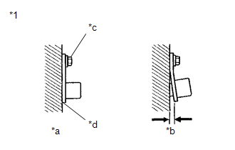
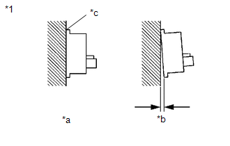
(b) Check the speed sensor installation.
OK:
There is no clearance between the sensor and the front steering knuckle RH.
The installation bolt is tightened properly.
Torque
8.5 N*m (87 kgf*cm, 75 in.*lbf)
| NG | |
REINSTALL OR REPLACE FRONT SPEED SENSOR RH |
|
|
6. |
CHECK FRONT SPEED SENSOR RH (CHECK FOR FOREIGN MATTER) |
(a) Remove the front speed sensor RH.
Click here
(b) Check the speed sensor tip.
OK:
The sensor tip is free of scratches, oil, and foreign matter.
NOTICE:
- If there is oil or foreign matter on the speed sensor, clean the speed sensor.
- If the speed sensor is damaged, replace the speed sensor with a new one.
- Check the speed sensor signal after cleaning or replacement.
Click here
| NG | |
CLEAN OR REPLACE FRONT SPEED SENSOR RH |
|
|
7. |
INSPECT BRAKE ACTUATOR ASSEMBLY (POWER SOURCE CIRCUIT) |
|
(a) Make sure that there is no looseness at the locking part and the connecting part of the connectors. OK: The connector is securely connected. |
|
(b) Disconnect the front speed sensor RH connector.
(c) Check both the connector case and the terminals for deformation and corrosion.
OK:
No deformation or corrosion.
(d) Turn the ignition switch to ON.
(e) Measure the voltage according to the value(s) in the table below.
Standard Voltage:
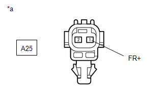
|
Tester Connection |
Condition |
Specified Condition |
|---|---|---|
|
A25-1 (FR+) - Body ground |
Ignition switch ON |
11 to 14 V |
| NG | |
GO TO STEP 10 |
|
|
8. |
INSPECT BRAKE ACTUATOR ASSEMBLY (GROUND CIRCUIT) |
|
(a) Measure the voltage according to the value(s) in the table below. Standard Voltage:
|
|
| NG | |
GO TO STEP 11 |
|
|
9. |
CHECK FRONT SPEED SENSOR ROTOR (FRONT AXLE HUB ASSEMBLY RH) (CHECK FOR FOREIGN MATTER) |
(a) Remove the front speed sensor rotor (front axle hub assembly RH).
Click here
(b) Check the speed sensor rotor.
OK:
The rotor is free of scratches, oil, and foreign matter.
NOTICE:
- If there is oil or foreign matter on the speed sensor rotor, clean the speed sensor rotor.
- If the speed sensor rotor is damaged, replace the speed sensor rotor with a new one.
- Check the speed sensor signal after cleaning or replacement.
Click here
HINT:
- The front speed sensor rotor is incorporated into the front axle hub assembly.
- If the front speed sensor rotor needs to be replaced, replace it together with the front axle hub assembly.
|
Result |
Proceed to |
|---|---|
|
OK |
A |
|
NG (The speed sensor rotor is damaged.) |
B |
|
NG (There is foreign matter on the speed sensor rotor.) |
C |
| A | |
REPLACE FRONT SPEED SENSOR RH |
| B | |
REPLACE FRONT AXLE HUB SUB-ASSEMBLY RH |
| C | |
CLEAN FRONT SPEED SENSOR ROTOR (FRONT AXLE HUB ASSEMBLY RH) |
|
10. |
CHECK HARNESS AND CONNECTOR (BRAKE ACTUATOR ASSEMBLY - FRONT SPEED SENSOR RH) |
(a) Turn the ignition switch off.
(b) Make sure that there is no looseness at the locking part and the connecting part of the connectors.
OK:
The connector is securely connected.
(c) Disconnect the A42 skid control ECU (brake actuator assembly) connector.
(d) Check both the connector case and the terminals for deformation and corrosion.
OK:
No deformation or corrosion.
(e) Measure the resistance according to the value(s) in the table below.
Standard Resistance:
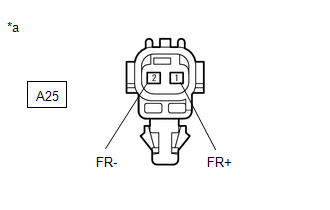
|
Tester Connection |
Condition |
Specified Condition |
|---|---|---|
|
A42-26 (FR-) - A25-2 (FR-) |
Always |
Below 1 Ω |
|
A42-26 (FR-) or A25-2 (FR-) - Body ground |
Always |
10 kΩ or higher |
| OK | |
REPLACE BRAKE ACTUATOR ASSEMBLY |
| NG | |
REPAIR OR REPLACE HARNESS OR CONNECTOR |
|
11. |
CHECK HARNESS AND CONNECTOR (BRAKE ACTUATOR ASSEMBLY - FRONT SPEED SENSOR RH) |
(a) Turn the ignition switch off.
(b) Make sure that there is no looseness at the locking part and the connecting part of the connectors.
OK:
The connector is securely connected.
(c) Disconnect the A42 skid control ECU (brake actuator assembly) connector.
(d) Check both the connector case and the terminals for deformation and corrosion.
OK:
No deformation or corrosion.
(e) Measure the resistance according to the value(s) in the table below.
Standard Resistance:
|
Tester Connection |
Condition |
Specified Condition |
|---|---|---|
|
A42-26 (FR-) - A25-2 (FR-) |
Always |
Below 1 Ω |
|
A42-26 (FR-) or A25-2 (FR-) - Body ground |
Always |
10 kΩ or higher |
| OK | |
REPLACE BRAKE ACTUATOR ASSEMBLY |
| NG | |
REPAIR OR REPLACE HARNESS OR CONNECTOR |
|
12. |
CHECK FRONT SPEED SENSOR LH INSTALLATION |
|
(a) Turn the ignition switch off. |
|
(b) Check the speed sensor installation.
OK:
There is no clearance between the sensor and the front steering knuckle LH.
The installation bolt is tightened properly.
Torque
8.5 N*m (87 kgf*cm, 75 in.*lbf)
| NG | |
REINSTALL OR REPLACE FRONT SPEED SENSOR LH |
|
|
13. |
CHECK FRONT SPEED SENSOR LH (CHECK FOR FOREIGN MATTER) |
(a) Remove the front speed sensor LH.
Click here
(b) Check the speed sensor tip.
OK:
The sensor tip is free of scratches, oil, and foreign matter.
NOTICE:
- If there is oil or foreign matter on the speed sensor, clean the speed sensor.
- If the speed sensor is damaged, replace the speed sensor with a new one.
- Check the speed sensor signal after cleaning or replacement.
Click here
| NG | |
CLEAN OR REPLACE FRONT SPEED SENSOR LH |
|
|
14. |
INSPECT BRAKE ACTUATOR ASSEMBLY (POWER SOURCE CIRCUIT) |
|
(a) Make sure that there is no looseness at the locking part and the connecting part of the connectors. OK: The connector is securely connected. |
|
(b) Disconnect the front speed sensor LH connector.
(c) Check both the connector case and the terminals for deformation and corrosion.
OK:
No deformation or corrosion.
(d) Turn the ignition switch to ON.
(e) Measure the voltage according to the value(s) in the table below.
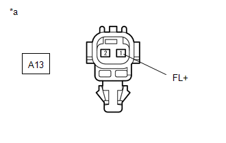
Standard Voltage:
|
Tester Connection |
Condition |
Specified Condition |
|---|---|---|
|
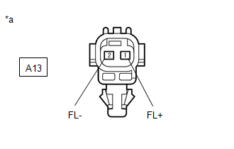
A13-1 (FL+) - Body ground |
Ignition switch ON |
11 to 14 V |
| NG | |
GO TO STEP 17 |
|
|
15. |
INSPECT BRAKE ACTUATOR ASSEMBLY (GROUND CIRCUIT) |
|
(a) Measure the voltage according to the value(s) in the table below. Standard Voltage:
|
|
| NG | |
GO TO STEP 18 |
|
|
16. |
CHECK FRONT SPEED SENSOR ROTOR (FRONT AXLE HUB ASSEMBLY LH) (CHECK FOR FOREIGN MATTER) |
(a) Remove the front speed sensor rotor (front axle hub assembly LH).
Click here
(b) Check the speed sensor rotor.
OK:
The rotor is free of scratches, oil, and foreign matter.
NOTICE:
- If there is oil or foreign matter on the speed sensor rotor, clean the speed sensor rotor.
- If the speed sensor rotor is damaged, replace the speed sensor rotor with a new one.
- Check the speed sensor signal after cleaning or replacement.
Click here
HINT:
- The front speed sensor rotor is incorporated into the front axle hub assembly.
- If the front speed sensor rotor needs to be replaced, replace it together with the front axle hub assembly.
|
Result |
Proceed to |
|---|---|
|
OK |
A |
|
NG (The speed sensor rotor is damaged.) |
B |
|
NG (There is foreign matter on the speed sensor rotor.) |
C |
| A | |
REPLACE FRONT SPEED SENSOR LH |
| B | |
REPLACE FRONT AXLE HUB SUB-ASSEMBLY LH |
| C | |
CLEAN FRONT SPEED SENSOR ROTOR (FRONT AXLE HUB ASSEMBLY RH) |
|
17. |
CHECK HARNESS AND CONNECTOR (BRAKE ACTUATOR ASSEMBLY - FRONT SPEED SENSOR LH) |
(a) Turn the ignition switch off.
(b) Make sure that there is no looseness at the locking part and the connecting part of the connectors.
OK:
The connector is securely connected.
(c) Disconnect the A42 skid control ECU (brake actuator assembly) connector.
(d) Check both the connector case and the terminals for deformation and corrosion.
OK:
No deformation or corrosion.
(e) Measure the resistance according to the value(s) in the table below.
Standard Resistance:
|
Tester Connection |
Condition |
Specified Condition |
|---|---|---|
|
A42-7 (FL-) - A13-2 (FL-) |
Always |
Below 1 Ω |
|
A42-7 (FL-) or A13-2 (FR-) - Body ground |
Always |
10 kΩ or higher |
| OK | |
REPLACE BRAKE ACTUATOR ASSEMBLY |
| NG | |
REPAIR OR REPLACE HARNESS OR CONNECTOR |
|
18. |
CHECK HARNESS AND CONNECTOR (BRAKE ACTUATOR ASSEMBLY - FRONT SPEED SENSOR LH) |
(a) Turn the ignition switch off.
(b) Make sure that there is no looseness at the locking part and the connecting part of the connectors.
OK:
The connector is securely connected.
(c) Disconnect the A42 skid control ECU (brake actuator assembly) connector.
(d) Check both the connector case and the terminals for deformation and corrosion.
OK:
No deformation or corrosion.
(e) Measure the resistance according to the value(s) in the table below.
Standard Resistance:
|
Tester Connection |
Condition |
Specified Condition |
|---|---|---|
|
A42-7 (FL-) - A13-2 (FL-) |
Always |
Below 1 Ω |
|
A42-7 (FL-) or A13-2 (FR-) - Body ground |
Always |
10 kΩ or higher |
| OK | |
REPLACE BRAKE ACTUATOR ASSEMBLY |
| NG | |
REPAIR OR REPLACE HARNESS OR CONNECTOR |
|
19. |
CHECK REAR SPEED SENSOR RH INSTALLATION |
|
(a) Turn the ignition switch off. |
|
(b) Check the speed sensor installation.
OK:
There is no clearance between the sensor and the rear axle hub.
HINT:
Because the rear axle hub and bearing assembly RH cannot be disassembled, if the rear speed sensor needs replacement, replace the rear axle hub and bearing assembly RH.
| NG | |
REPLACE REAR AXLE HUB AND BEARING ASSEMBLY RH |
|
|
20. |
INSPECT BRAKE ACTUATOR ASSEMBLY (POWER SOURCE CIRCUIT) |
|
(a) Make sure that there is no looseness at the locking part and the connecting part of the connectors. OK: The connector is securely connected. |
|
(b) Disconnect the rear speed sensor RH connector.
(c) Check both the connector case and the terminals for deformation and corrosion.
OK:
No deformation or corrosion.
(d) Turn the ignition switch to ON.
(e) Measure the voltage according to the value(s) in the table below.
Standard Voltage:
|
Tester Connection |
Condition |
Specified Condition |
|---|---|---|
|
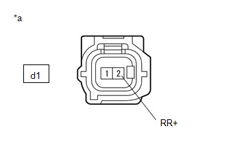
d1-2 (RR+) - Body ground |
Ignition switch ON |
11 to 14 V |
| NG | |
GO TO STEP 22 |
|
|
21. |
INSPECT BRAKE ACTUATOR ASSEMBLY (GROUND CIRCUIT) |
|
(a) Measure the voltage according to the value(s) in the table below. Standard Voltage:
|
|
| OK | |
REPLACE REAR AXLE HUB AND BEARING ASSEMBLY RH |
| NG | |
GO TO STEP 24 |
|
22. |
INSPECT SKID CONTROL SENSOR WIRE RH (NO. 1 PARKING BRAKE WIRE ASSEMBLY) |
|
(a) Turn the ignition switch off. |
|

(b) Make sure that there is no looseness at the locking part and the connecting part of the connectors.
OK:
The connector is securely connected.
(c) Remove the skid control sensor wire RH (No. 1 parking brake wire assembly).
(d) Check both the connector case and the terminals for deformation and corrosion.
OK:
No deformation or corrosion.
(e) Measure the resistance according to the value(s) in the table below.
Standard Resistance:
|
Tester Connection |
Condition |
Specified Condition |
|---|---|---|
|
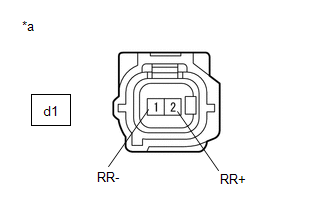
d1-1 (RR-) - dM1-2 (RR-) |
Always |
Below 1 Ω |
|
d1-1 (RR-) - dM1-1 (RR+) |
Always |
10 kΩ or higher |
|
d1-1 (RR-) or dM1-2 (RR-) - Body ground |
Always |
10 kΩ or higher |
NOTICE:
Check the speed sensor signal after replacement.
Click here
| NG | |
REPLACE SKID CONTROL SENSOR WIRE RH (NO. 1 PARKING BRAKE WIRE ASSEMBLY) |
|
|
23. |
CHECK HARNESS AND CONNECTOR (BRAKE ACTUATOR ASSEMBLY - SKID CONTROL SENSOR WIRE RH (NO. 1 PARKING BRAKE WIRE ASSEMBLY)) |
(a) Make sure that there is no looseness at the locking part and the connecting part of the connector.
OK:
The connector is securely connected.
(b) Disconnect the A42 skid control ECU (brake actuator assembly) connector.
(c) Check both the connector case and the terminals for deformation and corrosion.
OK:
No deformation or corrosion.
(d) Measure the resistance according to the value(s) in the table below.
Standard Resistance:
|
Tester Connection |
Condition |
Specified Condition |
|---|---|---|
|
A42-37 (RR-) - dM1-2 (RR-) |
Always |
Below 1 Ω |
|
A42-37 (RR-) or dM1-2 (RR-) - Body ground |
Always |
10 kΩ or higher |
| OK | |
REPLACE BRAKE ACTUATOR ASSEMBLY |
| NG | |
REPAIR OR REPLACE HARNESS OR CONNECTOR |
|
24. |
INSPECT SKID CONTROL SENSOR WIRE RH (NO. 1 PARKING BRAKE WIRE ASSEMBLY) |
|
(a) Turn the ignition switch off. |
|
(b) Make sure that there is no looseness at the locking part and the connecting part of the connectors.
OK:
The connector is securely connected.
(c) Remove the skid control sensor wire RH (No. 1 parking brake wire assembly).
(d) Check both the connector case and the terminals for deformation and corrosion.
OK:
No deformation or corrosion.
(e) Measure the resistance according to the value(s) in the table below.
Standard Resistance:
|
Tester Connection |
Condition |
Specified Condition |
|---|---|---|
|
d1-1 (RR-) - dM1-2 (RR-) |
Always |
Below 1 Ω |
|
d1-1 (RR-) - dM1-1 (RR+) |
Always |
10 kΩ or higher |
|
d1-1 (RR-) or dM1-2 (RR-) - Body ground |
Always |
10 kΩ or higher |
NOTICE:
Check the speed sensor signal after replacement.
Click here
| NG | |
REPLACE SKID CONTROL SENSOR WIRE RH (NO. 1 PARKING BRAKE WIRE ASSEMBLY) |
|
|
25. |
CHECK HARNESS AND CONNECTOR (BRAKE ACTUATOR ASSEMBLY - SKID CONTROL SENSOR WIRE RH (NO. 1 PARKING BRAKE WIRE ASSEMBLY)) |
(a) Make sure that there is no looseness at the locking part and the connecting part of the connector.
OK:
The connector is securely connected.
(b) Disconnect the A42 skid control ECU (brake actuator assembly) connector.
(c) Check both the connector case and the terminals for deformation and corrosion.
OK:
No deformation or corrosion.
(d) Measure the resistance according to the value(s) in the table below.
Standard Resistance:
|
Tester Connection |
Condition |
Specified Condition |
|---|---|---|
|
A42-37 (RR-) - dM1-2 (RR-) |
Always |
Below 1 Ω |
|
A42-37 (RR-) or dM1-2 (RR-) - Body ground |
Always |
10 kΩ or higher |
| OK | |
REPLACE BRAKE ACTUATOR ASSEMBLY |
| NG | |
REPAIR OR REPLACE HARNESS OR CONNECTOR |
|
26. |
CHECK REAR SPEED SENSOR LH INSTALLATION |
|
(a) Turn the ignition switch off. |
|
(b) Check the speed sensor installation.
OK:
There is no clearance between the sensor and the rear axle hub.
HINT:
Because the rear axle hub and bearing assembly LH cannot be disassembled, if the rear speed sensor needs replacement, replace the rear axle hub and bearing assembly LH.
| NG | |
REPLACE REAR AXLE HUB AND BEARING ASSEMBLY LH |
|
|
27. |
INSPECT BRAKE ACTUATOR ASSEMBLY (POWER SOURCE CIRCUIT) |
|
(a) Make sure that there is no looseness at the locking part and the connecting part of the connectors. OK: The connector is securely connected. |
|
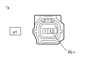
(b) Disconnect the rear speed sensor LH connector.
(c) Check both the connector case and the terminals for deformation and corrosion.
OK:
No deformation or corrosion.
(d) Turn the ignition switch to ON.
(e) Measure the voltage according to the value(s) in the table below.
Standard Voltage:
|
Tester Connection |
Condition |
Specified Condition |
|---|---|---|
|
e1-2 (RL+) - Body ground |
Ignition switch ON |
11 to 14 V |
| NG | |
GO TO STEP 29 |
|
|
28. |
INSPECT BRAKE ACTUATOR ASSEMBLY (GROUND CIRCUIT) |
|
(a) Measure the voltage according to the value(s) in the table below. Standard Voltage:
|
|
| OK | |
REPLACE REAR AXLE HUB AND BEARING ASSEMBLY LH |
| NG | |
GO TO STEP 31 |
|
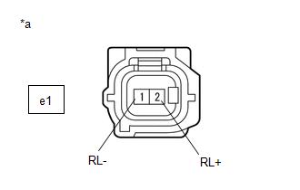
29. |
INSPECT SKID CONTROL SENSOR WIRE LH (NO. 2 PARKING BRAKE WIRE ASSEMBLY) |
|
(a) Turn the ignition switch off. |
|
(b) Make sure that there is no looseness at the locking part and the connecting part of the connectors.
OK:
The connector is securely connected.
(c) Remove the skid control sensor wire LH (No. 2 parking brake wire assembly).
(d) Check both the connector case and the terminals for deformation and corrosion.
OK:
No deformation or corrosion.
(e) Measure the resistance according to the value(s) in the table below.
Standard Resistance:
|
Tester Connection |
Condition |
Specified Condition |
|---|---|---|
|
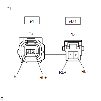
e1-1 (RL-) - eM1-2 (RL-) |
Always |
Below 1 Ω |
|
e1-1 (RL-) - eM1-1 (RL+) |
Always |
10 kΩ or higher |
|
e1-1 (RL-) or eM1-2 (RL-) - Body ground |
Always |
10 kΩ or higher |
NOTICE:
Check the speed sensor signal after replacement.
Click here
| NG | |
REPLACE SKID CONTROL SENSOR WIRE LH (NO. 2 PARKING BRAKE WIRE ASSEMBLY) |
|
|
30. |
CHECK HARNESS AND CONNECTOR (BRAKE ACTUATOR ASSEMBLY - SKID CONTROL SENSOR WIRE LH (NO. 2 PARKING BRAKE WIRE ASSEMBLY)) |
(a) Make sure that there is no looseness at the locking part and the connecting part of the connector.
OK:
The connector is securely connected.
(b) Disconnect the A42 skid control ECU (brake actuator assembly) connector.
(c) Check both the connector case and the terminals for deformation and corrosion.
OK:
No deformation or corrosion.
(d) Measure the resistance according to the value(s) in the table below.
Standard Resistance:
|
Tester Connection |
Condition |
Specified Condition |
|---|---|---|
|
A42-23 (RL-) - eM1-2 (RL-) |
Always |
Below 1 Ω |
|
A42-23 (RL-) or eM1-2 (RL-) - Body ground |
Always |
10 kΩ or higher |
| OK | |
REPLACE BRAKE ACTUATOR ASSEMBLY |
| NG | |
REPAIR OR REPLACE HARNESS OR CONNECTOR |
|
31. |
INSPECT SKID CONTROL SENSOR WIRE LH (NO. 2 PARKING BRAKE WIRE ASSEMBLY) |
|
(a) Turn the ignition switch off. |
|
(b) Make sure that there is no looseness at the locking part and the connecting part of the connectors.
OK:
The connector is securely connected.
(c) Remove the skid control sensor wire LH (No. 2 parking brake wire assembly).
(d) Check both the connector case and the terminals for deformation and corrosion.
OK:
No deformation or corrosion.
(e) Measure the resistance according to the value(s) in the table below.
Standard Resistance:
|
Tester Connection |
Condition |
Specified Condition |
|---|---|---|
|
e1-1 (RL-) - eM1-2 (RL-) |
Always |
Below 1 Ω |
|
e1-1 (RL-) - eM1-1 (RL+) |
Always |
10 kΩ or higher |
|
e1-1 (RL-) or eM1-2 (RL-) - Body ground |
Always |
10 kΩ or higher |
NOTICE:
Check the speed sensor signal after replacement.
Click here
| NG | |
REPLACE SKID CONTROL SENSOR WIRE LH (NO. 2 PARKING BRAKE WIRE ASSEMBLY) |
|
|
32. |
CHECK HARNESS AND CONNECTOR (BRAKE ACTUATOR ASSEMBLY - SKID CONTROL SENSOR WIRE LH (NO. 2 PARKING BRAKE WIRE ASSEMBLY)) |
(a) Make sure that there is no looseness at the locking part and the connecting part of the connector.
OK:
The connector is securely connected.
(b) Disconnect the A42 skid control ECU (brake actuator assembly) connector.
(c) Check both the connector case and the terminals for deformation and corrosion.
OK:
No deformation or corrosion.
(d) Measure the resistance according to the value(s) in the table below.
Standard Resistance:
|
Tester Connection |
Condition |
Specified Condition |
|---|---|---|
|
A42-23 (RL-) - eM1-2 (RL-) |
Always |
Below 1 Ω |
|
A42-23 (RL-) or eM1-2 (RL-) - Body ground |
Always |
10 kΩ or higher |
| OK | |
REPLACE BRAKE ACTUATOR ASSEMBLY |
| NG | |
REPAIR OR REPLACE HARNESS OR CONNECTOR |
 Yaw Rate Sensor (C1234,C1472,C1474)
DESCRIPTION
The skid control ECU (brake actuator assembly) receives signals from the yaw
rate and acceleration sensor (airbag sensor assembly) via CAN communication.
HINT:
If there is a malfuncti ...
 Low Power Supply Voltage Malfunction (C1241)
DESCRIPTION
If a malfunction is detected in the power supply circuit, the skid control ECU
(brake actuator assembly) stores this DTC and the fail-safe function prohibits ABS
operation. This DTC i ...
Other materials:
Toyota CH-R Service Manual > Audio And Visual System(for Radio Receiver Type): Portable Player cannot be Operated Using In-vehicle Device or Track Information
is not Displayed on In-vehicle Device
PROCEDURE
1.
CHECK USING ANOTHER "Bluetooth" AUDIO COMPATIBLE VEHICLE OF SAME MODEL
(a) Check if track information is displayed normally on another "Bluetooth" audio
compatible vehicle of the same model.
OK:
Track information is displayed no ...
Toyota CH-R Owners Manual > Before driving: Vehicle load limits
Vehicle load limits include total load capacity, seating capacity,
towing capacity and cargo capacity.
Total load capacity (vehicle capacity weight):
Total load capacity means the combined weight of occupants, cargo and luggage.
Seating capacity: 5 occupants (Front 2, Rear 3)
Seating capacity ...
Toyota C-HR (AX20) 2023-2026 Owner's Manual
Toyota CH-R Owners Manual
- For safety and security
- Instrument cluster
- Operation of each component
- Driving
- Interior features
- Maintenance and care
- When trouble arises
- Vehicle specifications
- For owners
Toyota CH-R Service Manual
- Introduction
- Maintenance
- Audio / Video
- Cellular Communication
- Navigation / Multi Info Display
- Park Assist / Monitoring
- Brake (front)
- Brake (rear)
- Brake Control / Dynamic Control Systems
- Brake System (other)
- Parking Brake
- Axle And Differential
- Drive Shaft / Propeller Shaft
- K114 Cvt
- 3zr-fae Battery / Charging
- Networking
- Power Distribution
- Power Assist Systems
- Steering Column
- Steering Gear / Linkage
- Alignment / Handling Diagnosis
- Front Suspension
- Rear Suspension
- Tire / Wheel
- Tire Pressure Monitoring
- Door / Hatch
- Exterior Panels / Trim
- Horn
- Lighting (ext)
- Mirror (ext)
- Window / Glass
- Wiper / Washer
- Door Lock
- Heating / Air Conditioning
- Interior Panels / Trim
- Lighting (int)
- Meter / Gauge / Display
- Mirror (int)
- Power Outlets (int)
- Pre-collision
- Seat
- Seat Belt
- Supplemental Restraint Systems
- Theft Deterrent / Keyless Entry

0.0114